System and method for controlling motion of spacecrafts

a technology for spacecraft and motion control, applied in the direction of navigation instruments, instruments for comonautical navigation, instruments, etc., can solve the problems of affecting the use of spacecraft, so as to achieve efficient determination of trajectory and optimize fuel consumption

Active Publication Date: 2014-02-18
MITSUBISHI ELECTRIC RES LAB INC
View PDF14 Cites 3 Cited by
  • Summary
  • Abstract
  • Description
  • Claims
  • Application Information

AI Technical Summary

Benefits of technology

[0017]Some embodiments of the invention are based on a realization that determining the trajectory for the object is a three-body problem, involving the earth, the moon and the object. It is further realized, that the motion of the object is qualitatively different in different regions of the space, because of different impact on the object by the earth and the moon. It is further realized that it is advantageous to use a stable manifolds of motion existing between the earth and the moon to optimize the fuel consumption.
[0018]Furthermore, it is specifically realized that the problem of determining the trajectories can be optimized by partitioning the trajectory into four phases of control. In each phase the object is subject to a specific combination of the forces, and thus, the determination of the trajectory can be handled efficiently by this partitioning.

Problems solved by technology

This approach leads to trajectories that can be completed in a small number of days, but with a suboptimal fuel consumption.
However, the three-body problem is chaotic and highly sensitive to initial conditions.
However, most of the trajectories take too long to be useful.
For example, methods based on weak-stability boundary (WSB) or methods based on bi-circular model transport the object very far away from earth (around 1.2 million K ms), which is undesirable due to limited capability of some ground-stations to monitor the object beyond the orbit of the moon.
Also, those methods concentrate on finding specific trajectories, and are not sufficient to design end-to-end control procedure.
Another method directly transfers the object onto stable manifolds, but lacks the flexibility to satisfy various orbit constraints.

Method used


Image

  • System and method for controlling motion of spacecrafts
  • System and method for controlling motion of spacecrafts
  • System and method for controlling motion of spacecrafts

Examples


Embodiment Construction

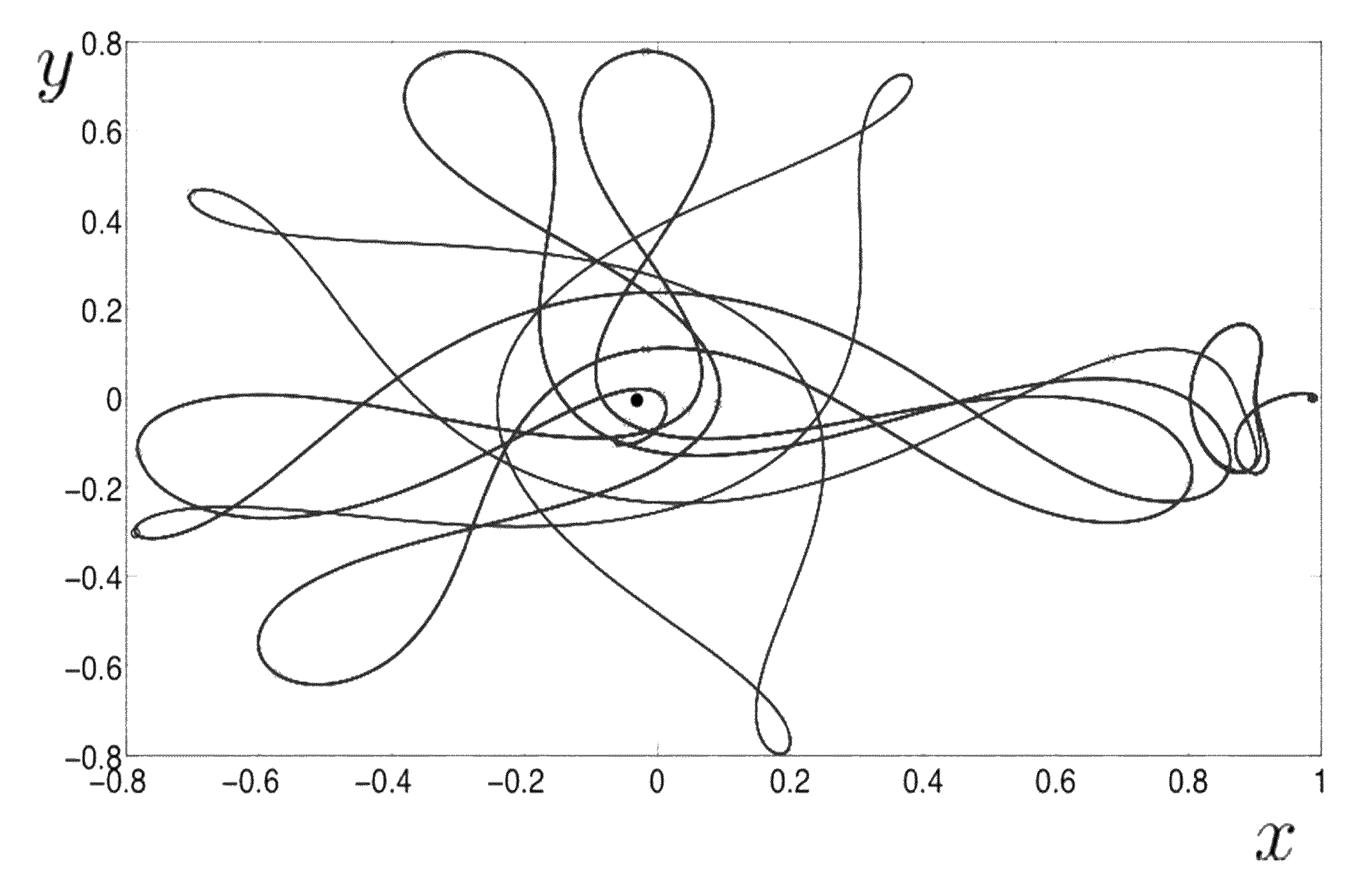
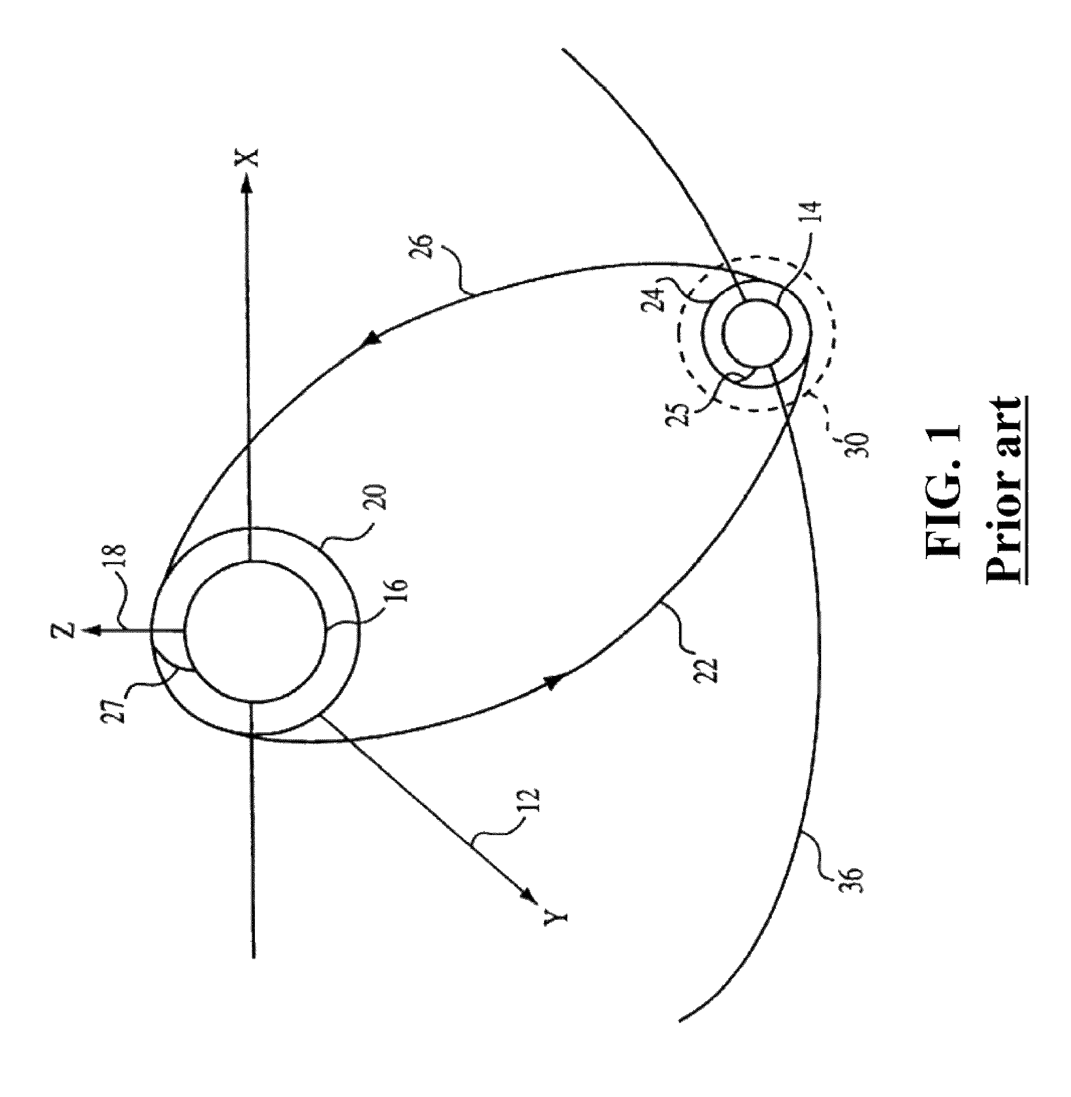
[0045]Various embodiments of an invention determine a trajectory for a motion of an object from a Geostationary Transfer Orbit (GTO) of the earth to an orbit around the moon, within a specified time. Some embodiments use planar circular restricted three-body problem (PCR3BP) model, involving the motion of the earth, the moon and the object for an initial trajectory. The PCR3BP model is a mathematical model used to determine the motion of the object (such as a space probe) in an earth-moon system. The system is four-dimensional system, and a state of the system is uniquely determined by four variables, usually the X and Y coordinates, and the X and Y velocities.

[0046]In various embodiments the effect of sun in the initial trajectory is neglected. However, some embodiments, after determining the initial trajectory, refines the trajectory using a more accurate model, which includes the effects of sun and other relevant planets.

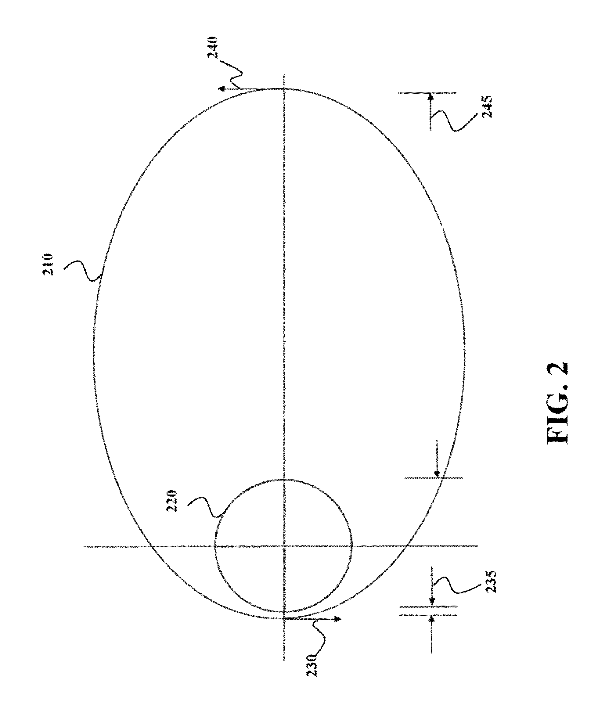
[0047]FIG. 2 shows a schematic of the GTO orbit 210 used by...


PUM


Abstract

A motion of an object is controlled from a geostationary transit orbit (GTO) of an earth to an orbit of a moon. A first trajectory of the motion of the object is determined from an intermediate orbit of an earth to a neighborhood of a stable manifold of a first Lagrange point (L1). A second trajectory of the motion of the object is determined from the GTO to the intermediate orbit. A third trajectory of the motion of the object is determined from the neighborhood to the stable manifold to an L1 orbit, and a fourth trajectory of the motion of the object is determined from the L1 orbit to the orbit of the moon. A trajectory from the GTO to the orbit of the moon is determined based on a combination of the first, the second, the third, and the fourth trajectories.

Description

RELATED APPLICATION[0001]This Application claims priority to U.S. Provisional Patent entitled, “System and Method for Controlling Motion of Spacecrafts” Application No. 61 / 590,626, filed on Jan. 25, 2012. The provisional application is incorporated herein by reference.FIELD OF THE INVENTION[0002]This invention relates generally to controlling motion of spacecrafts, and more particularly to controlling a motion of a spacecraft from an orbit of the earth to an orbit of a moon.BACKGROUND OF THE INVENTION[0003]Since the first lunar missions in the 1960s, the moon has been the object of interest of both scientific research and potential commercial development. During the 1980s, several lunar missions were launched by national space agencies. Interest in the moon is increasing with the advent of the multi-national space station making it possible to stage lunar missions from low earth orbit. However, continued interest in the moon and the feasibility of a lunar base depends, in part, on t...

Claims


Application Information

Patent Timeline
Patent Type & Authority Patents(United States)
IPC IPC(8): G05D1/10
CPCG05D1/10B64G1/00B64G1/242
Inventor GROVER, PIYUSHANDERSSON, CHRISTIAN
Owner MITSUBISHI ELECTRIC RES LAB INC
Why Eureka
Try Eureka