Gas intake device

a gas intake device and gas technology, applied in the direction of combustion air/fuel air treatment, machines/engines, mechanical equipment, etc., can solve the problems of high price of stiffening and increase the weight of the casing, and achieve good rigidity and fulfil a structural function

Active Publication Date: 2014-02-25
VALEO SYST DE CONTROLE MOTEUR +1
View PDF29 Cites 5 Cited by
  • Summary
  • Abstract
  • Description
  • Claims
  • Application Information

AI Technical Summary

Benefits of technology

[0019]Thus the plate, mounted directly on the cylinder head of the engine, which is a cold part of the engine, plays a part in cooling the valve by permitting exchanges of heat betwee

Problems solved by technology

Such stiffening is expensive and

Method used


Image

  • Gas intake device
  • Gas intake device
  • Gas intake device

Examples


Embodiment Construction

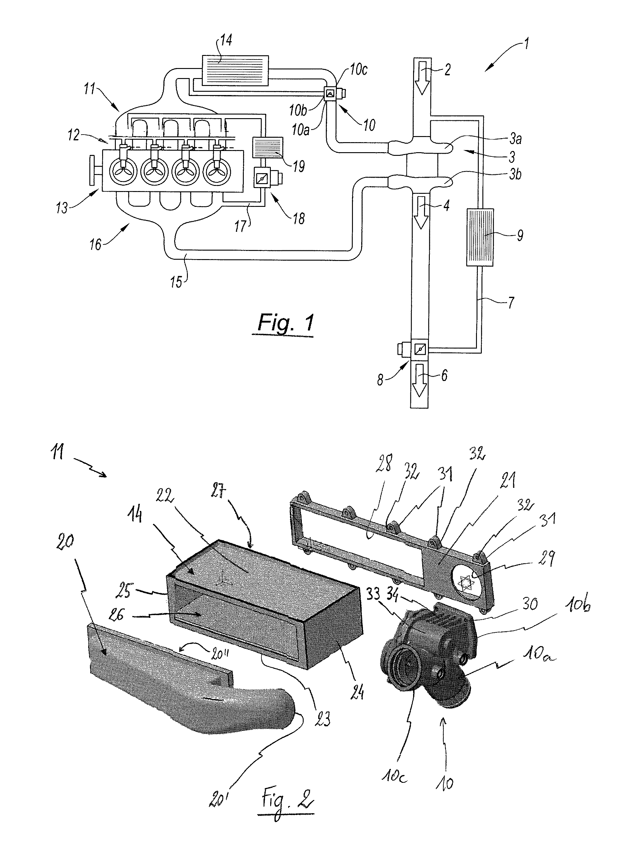
[0030]With reference to FIG. 1, the engine 1 of the invention comprises a combustion chamber 13, in this instance made up of four cylinders in which pistons are mounted such that they can move, as is well known. The engine inlet air 2 is admitted via a turbocharger 3 comprising a compressor 3a, driven by a turbine 3b, the latter being driven by the exhaust gases 4. Having driven the turbine 3b, the exhaust gases 4 are either discharged via exhaust pipes 6 or “recirculated”, that is to say reinjected into the inlet air stream 2. This exhaust gas recirculation is the said to be “low-pressure” exhaust gas recirculation. The EGR gases 7 are, for this purpose, tapped off at a valve 8, cooled in a low-pressure EGR heat exchanger 9 and injected into the inlet air stream 2 upstream of the compressor 3a. Mixing inlet air 2 with EGR gases 7 in this way makes it possible to reduce nitrogen oxides emissions.

[0031]The inlet gases 2, 7 therefore comprise, as they enter the compressor 3a, either o...


PUM


Abstract

A gas intake device for letting gases into an inlet volume of a cylinder head of a motor vehicle combustion engine includes a valve (10) for supplying the cylinder head with gas, this valve communicating with the inlet volume of the cylinder head directly and indirectly via a heat exchanger (14). The valve (10) and the heat exchanger (14) are mounted on a plate (21) intended to be mounted directly on the cylinder head. The device is compact and relatively insensitive to vibration.

Description

BACKGROUND OF THE INVENTION[0001]1. Field of the Invention[0002]The invention relates to a gas intake device for letting the said gases into the cylinder head of a motor vehicle combustion engine. The term “gases” is to be understood to mean air or a mixture of air and exhaust gas, to which liquid and / or gaseous fuel may have been added.[0003]2. Description of the Related Art[0004]A motor vehicle combustion engine comprises a combustion chamber, generally formed by a plurality of cylinders, in which a mixture of oxidant and fuel is burnt in order to generate engine work. The oxidant comprises air, which may or may not be compressed according to whether or not the engine is fitted with a turbocharger. The air may also be mixed with exhaust gases: these are then known as EGR (exhaust gas recirculation) gases. The gases admitted to the combustion chamber are termed inlet gases.[0005]The inlet gases are received at an intake manifold, the English-language term “intake manifold” being wi...

Claims


Application Information

Patent Timeline
IPC IPC(8): F02B47/08F02M15/00F02F1/42
CPCF02B29/0475F02M35/10216Y02T10/146F02M35/10255F02M25/0709F02M25/0707F02M35/10222F02M35/10268F02B29/0418F02M35/10078F02M26/05F02M26/06Y02T10/12
Inventor LEROUX, SAMUELLALLEMANT, MATHIEURIMPAU, ARNOLDWESTPHAL, CHRISTIAN
Owner VALEO SYST DE CONTROLE MOTEUR
Why Eureka
Try Eureka