Cab supporting apparatus of work machine

a technology for supporting apparatus and work machines, which is applied to roofs, furniture parts, tractors, etc., can solve the problems of increasing the number of parts, taking a lot of trouble with assembling and dismounting, and complicated structure of the movement limiting mechanism, so as to reduce manufacturing costs, simplify the structure, and increase the share rate

Active Publication Date: 2014-02-25
KOMATSU LTD
View PDF29 Cites 6 Cited by
  • Summary
  • Abstract
  • Description
  • Claims
  • Application Information

AI Technical Summary

Benefits of technology

[0010]The present invention was made for solving the above problems in the prior art. An objective of the present invention is to provide a cab supporting apparatus of a work machine which limits a movement of a cab frame by using a bracket for supporting a cab frame, and simplifies the structure.
[0012]Accordingly, in the cab supporting apparatus, the limiting means can be arranged by using a bracket for supporting the cab frame. Therefore, it is possible to make the structure of the cab supporting apparatus compact, and it is possible to simplify the structure of the cab supporting apparatus by reducing the number of the parts.
[0014]In the structure mentioned above, if the structure is made such that at least one of the lower limiting portion and the upper limiting portion forms a hook portion in a distal end thereof, and the hook portion limits the movement of the cab frame, it is possible to reliably regulate the position of the cab frame in the hook portion.
[0018]Further, when the work machine, for example, rolls over, an excessive load is applied at a high sharing rate to the rear portion of the cab frame. On the other hand, since the excessive load is applied only at a low sharing rate to the front portion of the cab frame, the excessive load can be borne even if the limitation of the moving range is cancelled. Accordingly, it is possible to simplify the structure as a whole of the cab supporting apparatus, and it is possible to reduce the manufacturing costs.

Problems solved by technology

Accordingly, the number of the parts is increased, the structure of the movement limiting mechanism is complicated, and there is a problem that it takes a lot of trouble with assembling and dismounting.

Method used


Image

  • Cab supporting apparatus of work machine
  • Cab supporting apparatus of work machine
  • Cab supporting apparatus of work machine

Examples


first embodiment

[0042]First, a description will be given of a first embodiment with reference to FIGS. 1 to 9.

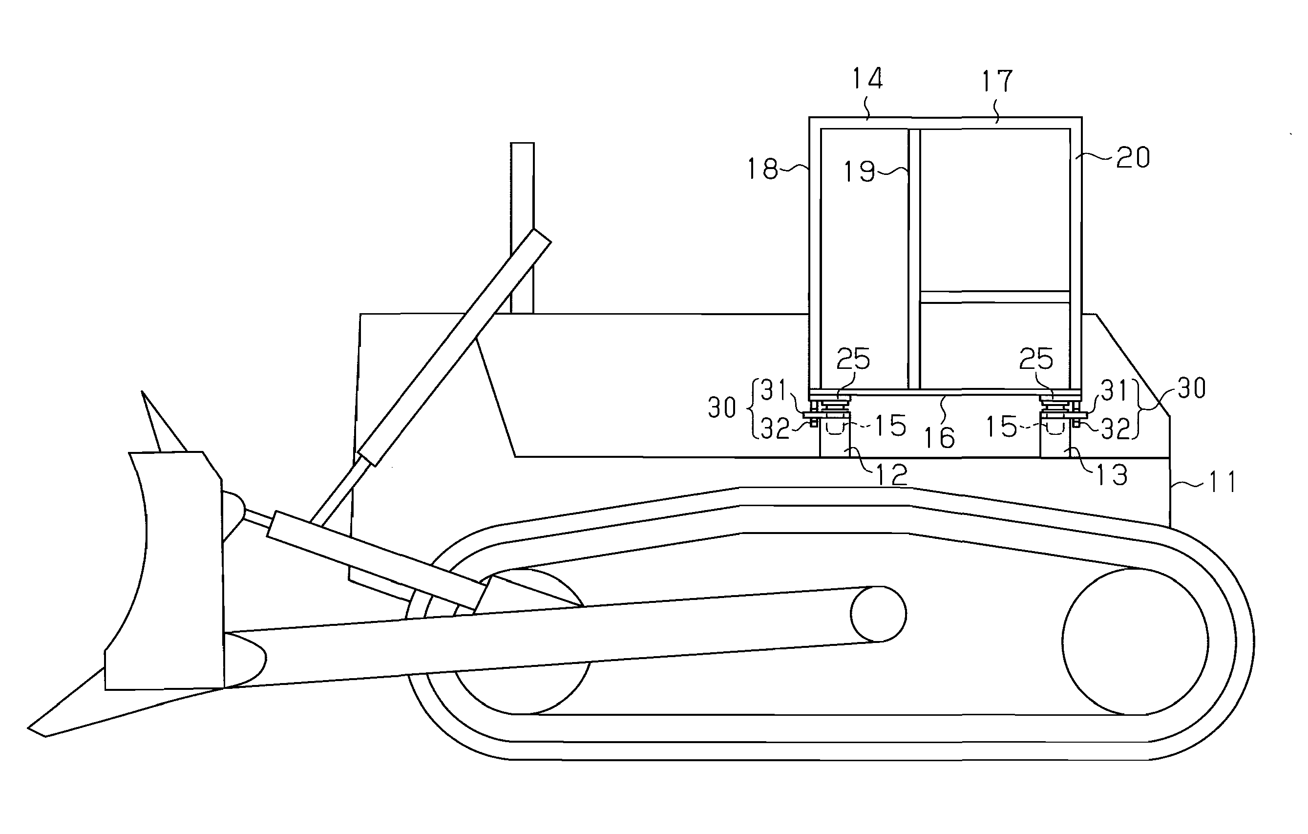
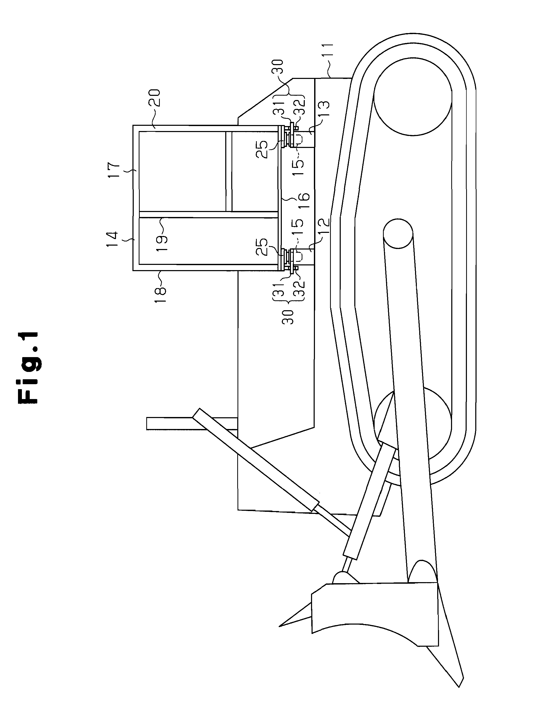
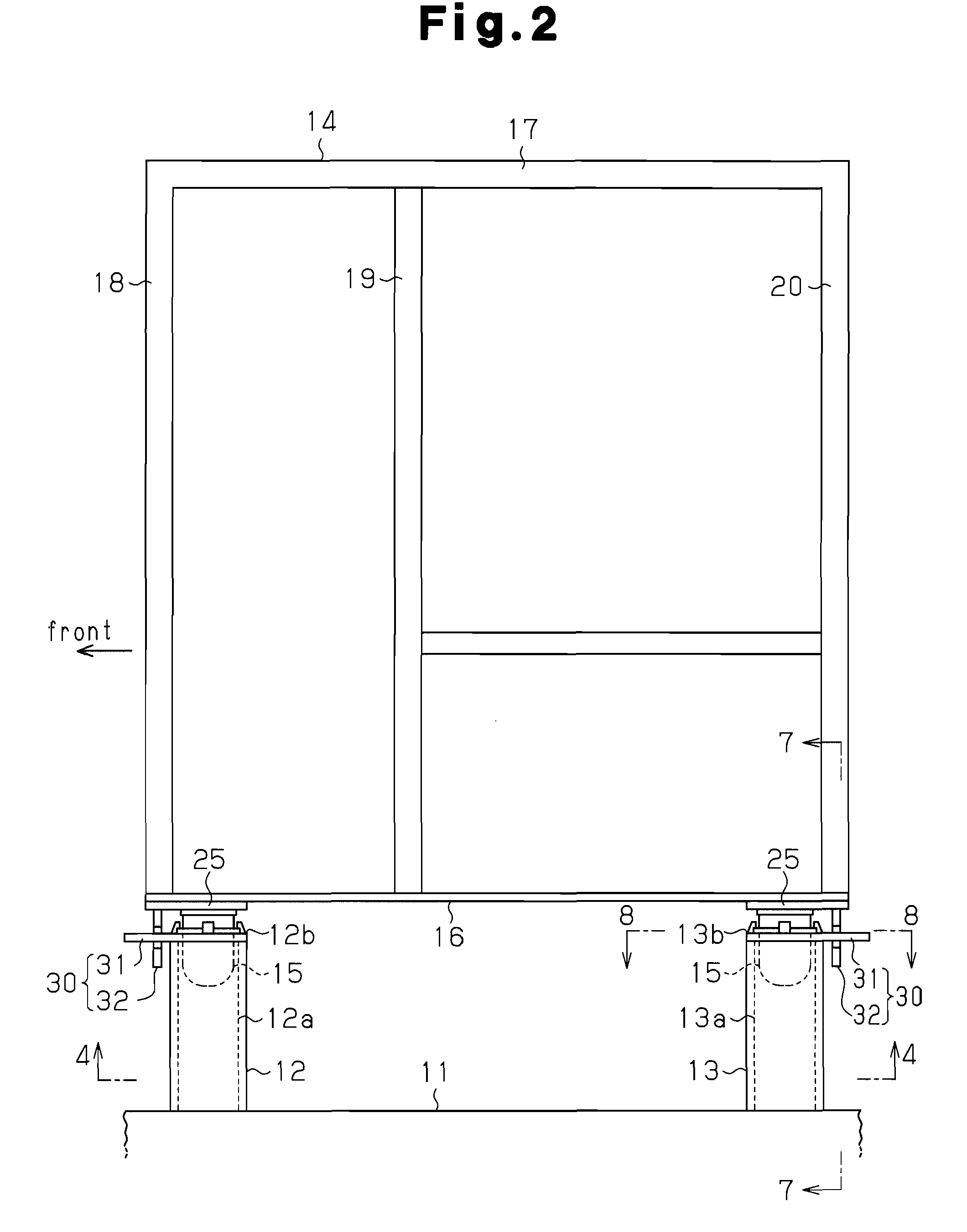
[0043]As shown in FIGS. 1 to 3 and 5, in a crawler dozer in accordance with the first embodiment, pairs of right and left metal brackets 12 and 13 are fixed at four positions on a vehicle body frame 11 so as to be spaced from each other in such a manner as to correspond to four corners of a bottom portion of a cab frame 14.

[0044]As shown in FIGS. 1 to 4, a cab frame 14 is supported on each of the brackets 12 and 13 with a damper 15 serving as vibration proofing mount means. The cab frame 14 is provided with a floor portion 16 and a ceiling portion 17. Right and left front pillars 18, intermediate pillars 19 and rear pillars 20 are arranged between the floor portion 16 and the ceiling portion 17 of the cab frame 14. Each of the brackets 12 and 13 and the dampers 15 are positioned immediately below the front pillars 18 and the rear pillars 20.

[0045]As shown in FIGS. 4 and 5, the brackets 12 a...

second embodiment

[0068]Next, a description will be given of a second embodiment in accordance with this invention.

[0069]In this case, in each of the second embodiment and the following embodiments and modified embodiments, a description will be given mainly of different portions from the first embodiment.

[0070]In the second embodiment, the structure is made such that the hook portion 32c is omitted in the lower limiting portions 31 in the front and the rear, as shown in FIG. 10. In other words, the lower limiting portion 31 has a recess 33 formed by a notch in a center in the lateral direction of the vehicle body frame in a front end or a rear end of the lower plates 12b and 13b. The upper limiting portion 32 corresponding to the lower limiting portion 31 has a recess 34 provided with a hook portion 32c. In accordance with this structure, the position of the cab frame 14 is limited in the vertical direction.

[0071]Since the hook portion 31c of the lower limiting portion 31 does not exist, it is possi...

third embodiment

[0072]In a third embodiment, the structure is made such that a positional relation in the front and rear movement limiting mechanisms 30, that is, a protruding direction of the front and rear lower limiting portions 31 is inverted back to front in comparison with the first embodiment, as shown in FIG. 11.

[0073]In accordance with this structure, the same advantages as the first embodiment are obtained.


PUM


Abstract

A cab frame (14) is supported on brackets (12, 13) provided at a plurality of positions of a vehicle body frame (11) with dampers (15). Movement limiting mechanisms (30) for limiting a movement at least in a vertical direction of the cab frame (14) are provided between the brackets (12, 13) and the cab frame (14). Further, the movement limiting mechanisms (30) are provided at least at two positions. Each movement limiting mechanism (30) includes a lower limiting portion (31) arranged close to the brackets (12, 13) and constituted by a plate member, and an upper limiting portion (32) arranged close to the cab frame (14) and constituted by a plate member in the same manner. The lower limiting portion (31) is integrally structured with the brackets (12, 13). Recesses (33, 34) are formed in a side edge of at least one of the lower limiting portion (31) and the upper limiting portion (32), and the limiting portion in the other limiting portion is positioned within the recesses (33, 34). Accordingly, in the cab supporting apparatus of a work machine, the movement limiting mechanism (30) is arranged by using the brackets (12, 13) for supporting the cab frame (14). Therefore, it is possible to simplify the structure of the cab supporting apparatus by reducing the number of the parts, and it is possible to make the structure compact. Accordingly, even in a compact work machine, the cab supporting apparatus is easily mounted.

Description

FIELD OF THE INVENTION[0001]The present invention relates to an operator's cab supporting apparatus of a work machine for supporting a cab frame on a vehicle body frame, in the work machine, for example, a crawler dozer.BACKGROUND OF THE INVENTION[0002]Generally, in the work machine such as the crawler dozer, a bracket is fixed at a plurality of positions on a vehicle body frame, and a cab frame is supported on the bracket. A damper is interposed between each of the brackets and the cab frame, and a vibration and an impact transmitted to the cab frame are damped by the damper. In each of the dampers, there is installed a movement limiting mechanism for limiting a movement of the cab frame in a vertical direction, a front-rear direction, and a lateral direction. Further, when a great load is applied to the cab frame from the outside in the case that the work machine rolls over by any chance, the movement of the cab frame in the vertical direction or the like is limited within a prede...

Claims


Application Information

Patent Timeline
Patent Type & Authority Patents(United States)
IPC IPC(8): B60J7/00F16M1/00B60N2/00B60K37/00B62D33/00F16M3/00F16M5/00
CPCE02F9/166
Inventor KAMIMAE, TAKESHI
Owner KOMATSU LTD
Why Eureka
Try Eureka