Tunable voltage-controlled pseudo-resistor

a pseudo-resistor and voltage control technology, applied in the direction of frequency-independent attenuators, pulse automatic control, electrical apparatus, etc., can solve the problems of large area, instability in process variations, and not cost effective to realize such a high resistance, so as to reduce cost and power consumption

Inactive Publication Date: 2014-02-25
NAT CENT UNIV
View PDF5 Cites 5 Cited by
  • Summary
  • Abstract
  • Description
  • Claims
  • Application Information

AI Technical Summary

Benefits of technology

[0015]In order to solve the problem of the prior art, the present invention provides a tunable voltage-controlled pseudo-resistor structure, comprising a symmetric PMOS transistor circuit and an auto-tuning circuit connected in series. The input of the auto-tuning circuit is connected to the central position Vf of the PMOS transistor circuit with its output Vg. The purpose of this design is to keep Vg−Vf at a constant value, so that the PMOS transistor circuit may produce Body Effect through various different bulk voltages. Through this auto-tuning circuit, Vg and Vf are kept constant to make currents of transistors to produce compensation effect, so regardless of Va>Vb or Va<Vb, a large resistance can be maintained.
[0018]Compared with the prior art, the present invention provides a tunable voltage-controlled pseudo-resistor structure, having the following advantages:1. having high and tunable resistance;2. Vab DC drift rejection; and3. enlarged range of input voltage.
[0019]The pseudo-resistor of the present invention is provided with the symmetric voltage-resistance characteristics, capable of maintaining constant resistance under high input voltage, and is suitable for use in applications requiring very low cut-off frequency. As such, it can not only be utilized in audio, analog, and biomedical applications, but it can also have wide range of input voltage, hereby providing tunable resistance and achieving reduction of cost and power consumption.

Problems solved by technology

However, presently, regardless of using off-the-shelf devices or standard cells on a chip, it is rather not cost effective to realize such a high resistance.
To place passive elements on a chip is a way of solution, but this will occupy a quite a large area.
In addition, high resistance can also be achieved through series-connecting MOS transistors of long length, but that also requires a large area and instability in process variations.

Method used


Image

  • Tunable voltage-controlled pseudo-resistor
  • Tunable voltage-controlled pseudo-resistor
  • Tunable voltage-controlled pseudo-resistor

Examples


Embodiment Construction

[0034]The purpose, construction, features, functions and advantages of the present invention can be appreciated and understood more thoroughly through the following detailed descriptions with reference to the attached drawings.

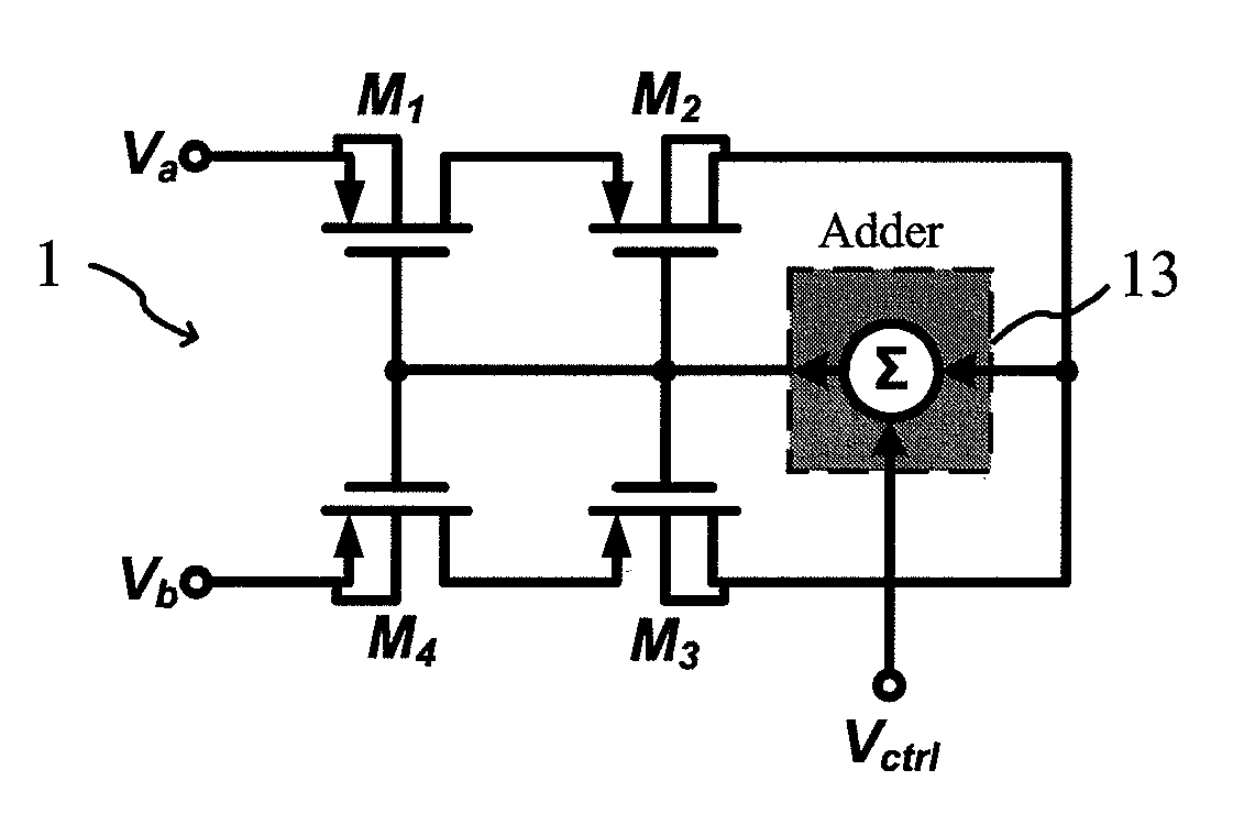
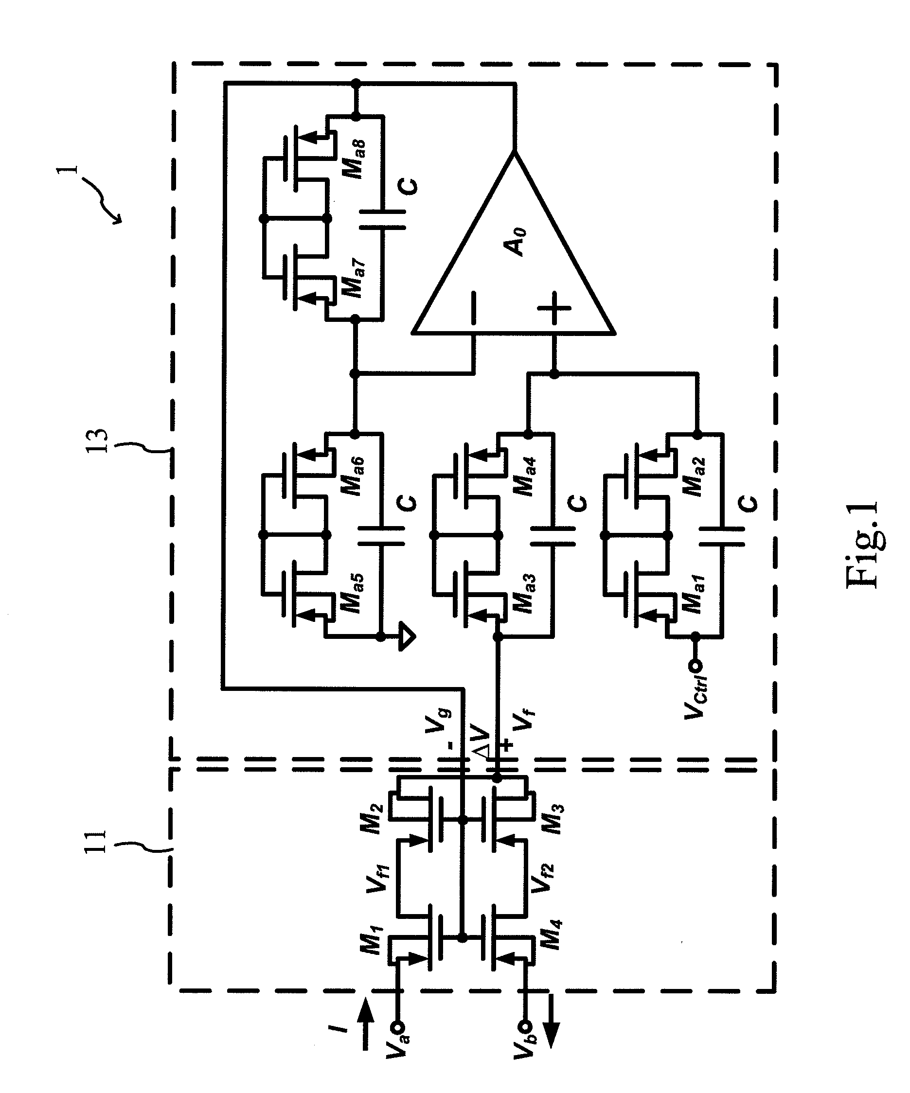
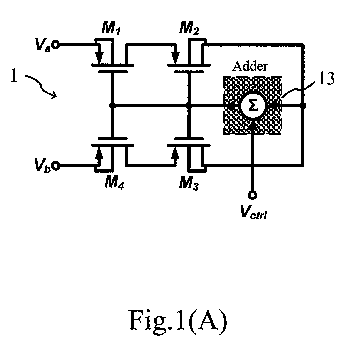
[0035]Refer to FIG. 1 and FIG. 1(A) for a circuit diagram of a tunable voltage-controlled pseudo-resistor structure according to the present invention. As shown in FIGS. 1 and 1(A), the tunable voltage-controlled pseudo-resistor structure 1 includes a symmetric PMOS transistor circuit (11) and an auto-tuning circuit (13) connected in series. The PMOS transistor circuit is formed by four PMOS elements (M1,M2,M3,M4) connected in series; while the auto-tuning circuit is an analog adder formed by an amplifier and four sets of active type resistors (Ma1˜Ma8) and capacitors connected in parallel. In addition, the input terminal of the auto-tuning circuit is at a central position Vf of the PMOS transistor circuit having output Vg. Its purpose is to keep Vg−Vf at cons...


PUM


Abstract

A tunable voltage-controlled pseudo-resistor structure, comprising: a symmetric PMOS transistor circuit and an auto-tuning circuit connected in series. Input of the auto-tuning circuit is connected to a central position Vf of the PMOS transistor circuit having its output Vg, with its purpose of keeping Vg−Vf at a constant value. The PMOS transistor circuit may produce body effect through various different bulk voltages. Through the auto-tuning circuit, Vg and Vf are kept constant to make current of transistor to produce compensation effect, such that regardless of Va>Vb or Va<Vb, a large resistance is maintained. Through utilizing the tunable voltage-controlled pseudo-resistor structure, constant resistance can be maintained under high input voltage, hereby reducing drifting of common-mode voltage, in achieving a superior resistance effect.

Description

BACKGROUND OF THE INVENTION[0001]1. Field of the Invention[0002]The present invention relates to a tunable voltage-controlled pseudo-resistor, and in particular to a tunable voltage-controlled pseudo-resistor, that is composed mainly of series-connected PMOS elements operated in sub-threshold regions in cooperation with an auto-tuning circuit, so that the pseudo-resistor is able to overcome the variations of manufacturing process and drift of common-mode voltage, in achieving symmetric voltage-resistance characteristics, while maintaining constant resistance under high input voltage.[0003]2. The Prior Arts[0004]In general, the active type resistor used for testing in CMOS manufacturing process is operated in a triode region, with its aim of providing a resistance as small as possible, so that the switching circuit can be designed to lower its resistance and noise. Usually, in an analog front-end circuit for biomedical or audio application, a very large resistance is required to achi...

Claims


Application Information

Patent Timeline
Patent Type & Authority Patents(United States)
IPC IPC(8): H03L5/00
CPCH03H11/245H03H11/53
Inventor SHIUE, MUH-TIANYAO, KAI-WENGONG, CIHUN-SIYONG
Owner NAT CENT UNIV
Why Eureka
Try Eureka