Determination of the burning duration of an ignition spark

a technology of ignition spark and burning duration, which is applied in the direction of engine ignition, other installations, instruments, etc., can solve the problems of inability to directly measure the duration of ignition spark, and achieve the effects of preventing substantially slow or delayed combustion, reducing the variance of combustion process, and reducing the risk of ignition failur

Active Publication Date: 2014-03-04
GE JENBACHER
View PDF11 Cites 1 Cited by
  • Summary
  • Abstract
  • Description
  • Claims
  • Application Information

AI Technical Summary

Benefits of technology

[0026]That prevents substantially slow or delayed combustion and further results in a lesser variance in the combustion process and thus more complete combust

Problems solved by technology

Those possible ways of directly measuring the ignition spark duration are not possible with most ignition systems, more especially in the case of central ignition sy

Method used


Image

  • Determination of the burning duration of an ignition spark
  • Determination of the burning duration of an ignition spark
  • Determination of the burning duration of an ignition spark

Examples


Embodiment Construction

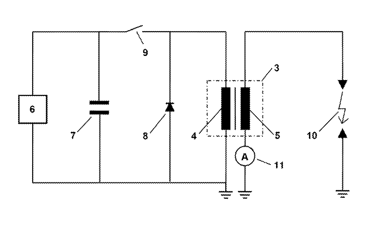
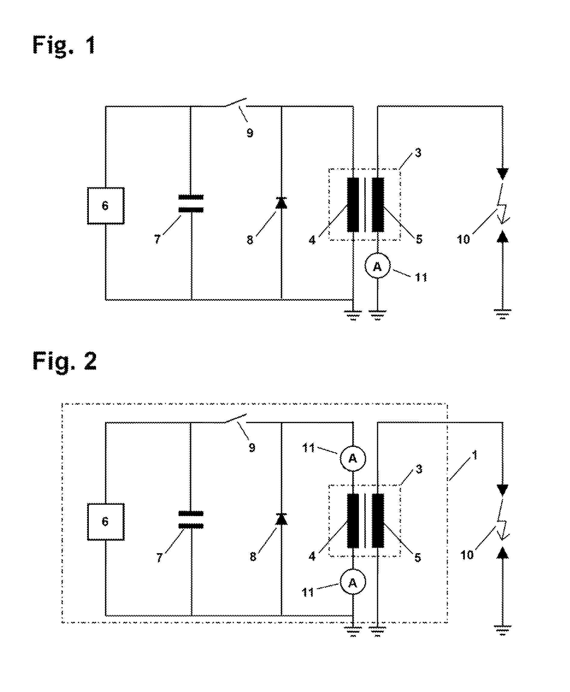
[0033]FIG. 2 shows an ignition device 1 according to the invention, in which the method of operating the conventional ignition device of FIG. 1 could not be used at all. The same components as in FIG. 1 are denoted by the same references. According to the invention, it is now provided that at least one current measuring device (ammeter) 11 is connected to the primary side 4 of the high voltage transformer 3. FIG. 2 shows two alternative positions for the location of the current measuring device 11. In that case, the current measuring device for the primary current can be selectively effected, for example, with a current transducer or with a measuring resistor in relation to ground.

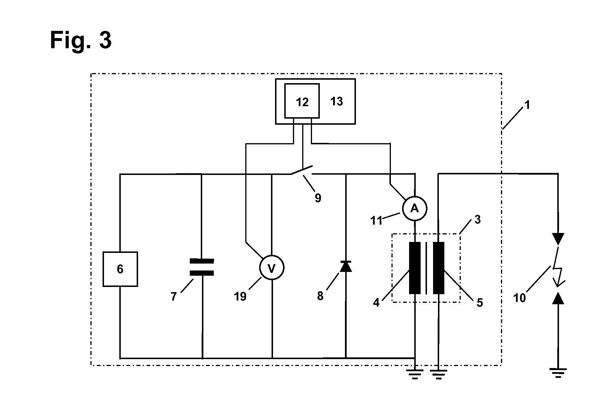
[0034]FIG. 3 shows a possible way of regulating the primary energy feed for optimizing the ignition spark energy and the ignition spark burning duration by the ignition spark burning duration measurement procedure by the evaluation provided according to the invention of the primary current measurement. In ...


PUM


Abstract

An ignition device has a high voltage transformer having a primary side and a secondary side, of which the primary side is connected to a high voltage source and the secondary side is connected to a spark path to provide the ignition spark. The time variation in the primary current flowing on the primary side is measured and subdivided at least into a spark burning phase and a subsequent free-running phase of the high voltage transformer. The transition from the spark burning phase into the free-running phase is equated to the moment of extinction of the ignition spark. The time variation of the primary current in the spark burning phase is mapped by a first function and in the free-running phase by a second function, and the intersection point of the two functions is equated to the moment of extinction of the ignition spark.

Description

BACKGROUND OF THE INVENTION[0001]The invention concerns a method of determining the moment of extinction of an ignition spark of an ignition device for an internal combustion engine. The ignition device has a high voltage transformer having a primary side and a secondary side, of which the primary side is connected to a high voltage source and the secondary side is connected to a spark path to provide the ignition spark and an ignition device for an internal combustion engine. The high voltage transformer is, in particular, a coil having a primary side and a secondary side. A high voltage source is electrically connected to the primary side, and a spark path is electrically connected to the secondary side. The time variation in the primary current flowing on the primary side is measured and subdivided at least into a spark burning phase and a subsequent free-running phase of the high voltage transformer, and the transition from the spark burning phase into the free-running phase is ...

Claims


Application Information

Patent Timeline
IPC IPC(8): F02P3/05
CPCF02P17/12F02P3/04F02P3/0853
Inventor GSCHIRR, ARNO
Owner GE JENBACHER
Why Eureka
Try Eureka