Spring clip retention systems suitable for usage within vehicles and guided munitions

a technology of retention system and spring clip, which is applied in the field of mounting system, can solve the problems of affecting the proper operation of the munition, affecting the assembly process of the overall munition, and presenting essentially the same drawbacks, and achieves the effect of increasing the width

Active Publication Date: 2014-03-04
RAYTHEON CO
View PDF39 Cites 53 Cited by
  • Summary
  • Abstract
  • Description
  • Claims
  • Application Information

AI Technical Summary

Benefits of technology

[0005]Embodiment of a spring clip retention system are provided for securing a generally cylindrical component in a desired position. In one embodiment, the spring clip retention system includes a captive feature and a spring clip. The captive feature includes opposing ledges and a channel, which is formed beneath and which is partially enclosed by the opposing ledges. The spring clip includes opposing retainer arms, which is configured to receive and resiliently retain the generally cylindrical component therebetween, and a base portion, which extends between the opposing retainer arms and received within the channel. The spring clip deflects outward and increases in width when the generally cylindrical component is inserted between the opposing retainer arm. The base portion the base portion abutting the undersides of the opposing ledges when the spring clip is deflected outward by insertion of the generally cylindrical component to prevent disengagement of the base portion from the captive feature in a direction substantially normal to the longitudinal axis of the channel.
[0006]Embodiments of a guided munition are further provided. In one embodiment, the guided munition includes a munition mounting structure, a generally cylindrical component, and a spring clip retention system. The spring clip retention system includes, in turn, a captive feature and a spring clip. The captive feature is fixed coupled to the munition mounting structure and includes an outer surface, an inner channel, and a longitudinal opening extending from the outer surface to the inner channel. The width of the inner channel exceeds the width of the longitudinal opening. The spring clip includes opposing retainer arms, which resiliently retaining the generally cylindrical component therebetween; and a base portion, which extends from the opposing retainer arms, through the longitudinal opening, and into the inner channel in a first direction. The spring clip deflects outward when the generally cylindrical component is inserted between the opposing retainer arms. The maximum width of the base portion exceeds the width of the longitudinal opening when the spring clip is deflected outward by insertion of the generally cylindrical component to prevent disengagement of the base portion from the captive feature in a second direction substantially opposite the first direction to secure the generally cylindrical component to the munition mounting structure.

Problems solved by technology

However, the usage of adhesives often requires surface cleaning and curing processes that add undesired complexity and delay to the overall munition assembly process.
In addition, high strength, high temperature, industrial-grade adhesives may outgass and release caustic chemicals into the munition's interior over time, which can potentially interfere with proper operation of the munition.
The spring clips can be adhesively bonded to internal structure of the guided munition; however, this presents essentially the same drawbacks as does bonding the cylindrical component directly to the internal structure.
Fasteners are commonly utilized to mechanically secure spring clips in place; however, the usage of fasteners adds undesired cost, complexity, and part count to the guided munition.
Furthermore, in the case of threaded fasteners, the formation of mating threads within the munition's internal structure adds further complexity to the fabrication process and, in certain cases, may be prohibited by spatial restrictions.
As a still further disadvantage, the mechanical fastening of spring clips to a munition's internal structure is generally not amenable to automation and consequently increases human touch requirements during the assembly process.

Method used


Image

  • Spring clip retention systems suitable for usage within vehicles and guided munitions
  • Spring clip retention systems suitable for usage within vehicles and guided munitions
  • Spring clip retention systems suitable for usage within vehicles and guided munitions

Examples


Embodiment Construction

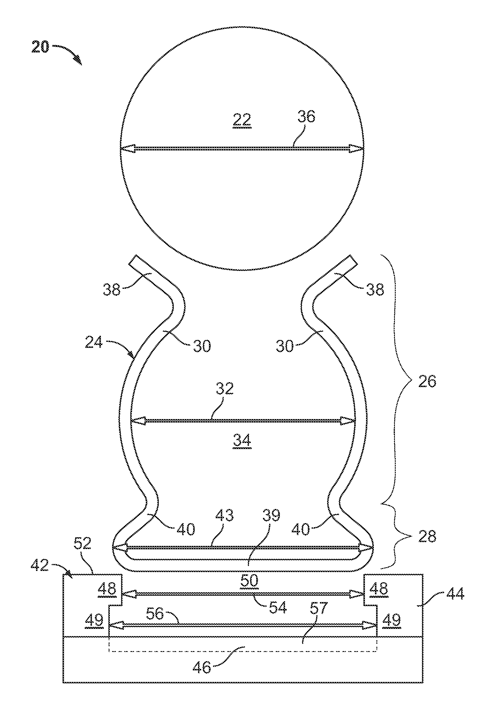
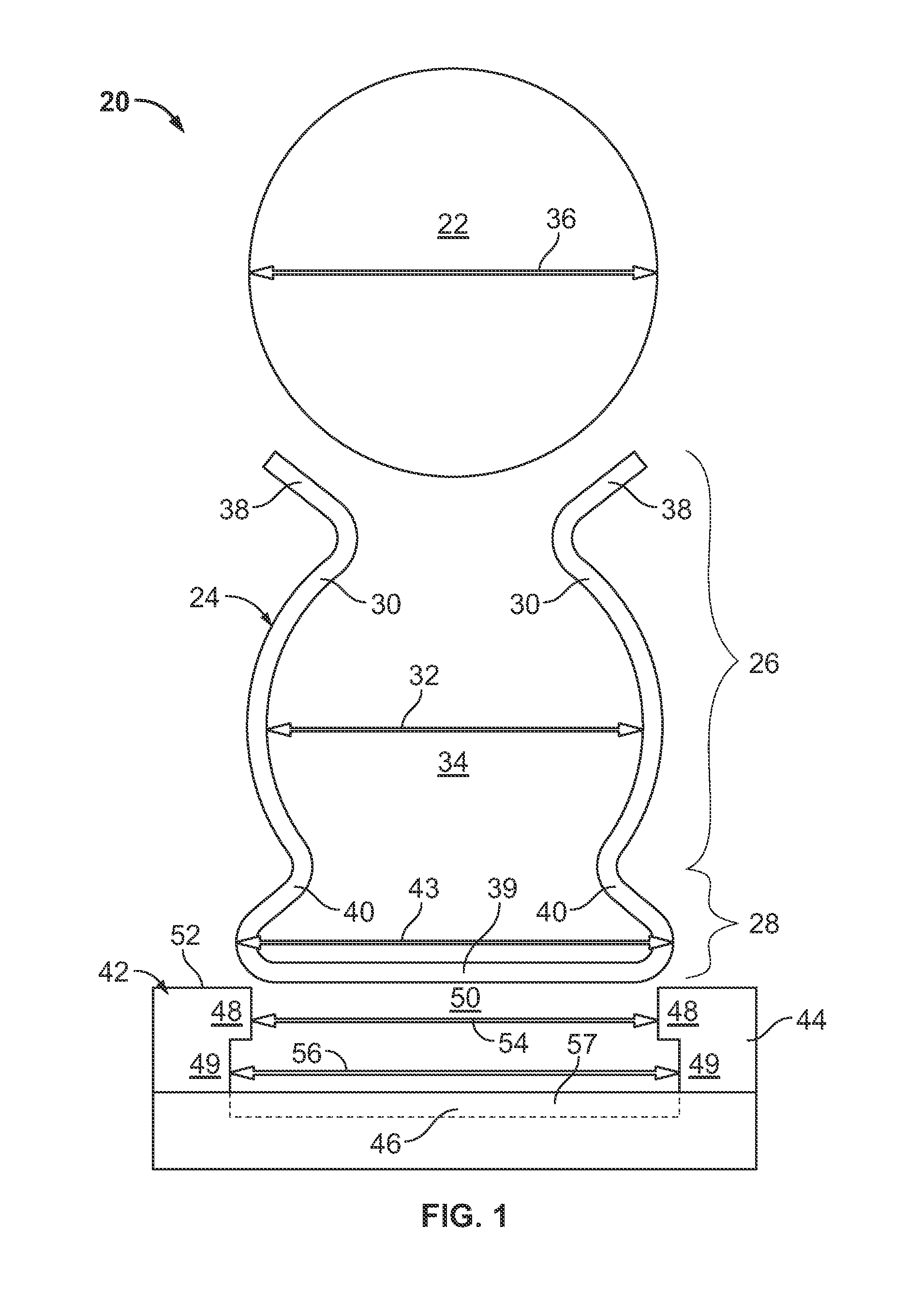
[0013]The following Detailed Description is merely exemplary in nature and is not intended to limit the invention or the application and uses of the invention. Furthermore, there is no intention to be bound by any theory presented in the preceding Background or the following Detailed Description.

[0014]FIGS. 1 and 2 are exploded end and isomeric views, respectively, of a spring clip retention system 20 and a generally cylindrical component 22 (shown in FIG. 1 only) illustrated in accordance with an exemplary embodiment of the present invention. Notably, spring clip retention system 20 is capable of retaining cylindrical component 22 (FIG. 1) in a desired position, such as against or adjacent another fabricated component, in a highly secure manner and without the usage of adhesives or threaded fasteners. Spring clip retention system 20 is also relatively lightweight, compact, and inexpensive to produce. For at least these reasons, spring clip retention system 20 is well-suited for usa...


PUM


Abstract

Embodiments of a spring clip retention system are provided for securing a generally cylindrical component, as are embodiments of a guided munition including a spring clip retention system. In one embodiment, the spring clip retention system includes a captive feature and a spring clip. The captive feature includes opposing ledges and a channel formed beneath and partially enclosed by the opposing ledges. The spring clip includes opposing retainer arms and a base portion, which extends between the opposing retainer arms and which is received within the channel. The spring clip deflects outward when the component is inserted between the opposing retainer arms. The base portion abuts the undersides of the opposing ledges when the spring clip is deflected outward by insertion of the component to prevent disengagement of the base portion from the captive feature in a direction substantially normal to the longitudinal axis of the channel.

Description

TECHNICAL FIELD[0001]The following disclosure relates generally to mounting systems and, more particularly, to spring clip retention systems that enable various objects to be removably secured within guided munitions, motor vehicles, and other platforms without the usage of adhesives or threaded fasteners.BACKGROUND[0002]Modern guided munitions commonly incorporate different types of components having generally cylindrical outer geometries, such as electromagnetic interference suppressor cores (e.g., ferrite beads) and hardline connections (e.g., cryogenic gas lines). During assembly of the guided munition, the cylindrical components are mounted within the munition's casing or shell adjacent other fabricated components. The mounting means utilized to retain a given cylindrical component in a desired position within the guided munition preferable does so in a highly secure manner to ensure that the component does not become dislodged or displaced when subjected to considerable loadin...

Claims


Application Information

Patent Timeline
Patent Type & Authority Patents(United States)
IPC IPC(8): F16L3/00
CPCF16B2/245F16L3/13F42B33/001F42B15/00F16B9/023F16L3/24F16L3/243
Inventor HERNANDEZ, CHRISTOPHER L.EGBERT, RYAN A.
Owner RAYTHEON CO
Why Eureka
Try Eureka