

Microfluidic driving system
a driving system and microfluidic technology, applied in the direction of machines/engines, electrostatic separation, chemical/physical processes, etc., can solve the problems of limiting the promotion and application of dc electroosmotic flows, electrode polarization, and the development potential as well as the application value cannot be ignored, so as to reduce flow resistance, improve the performance of ac electroosmotic flows, and effectively extend life-time
- Summary
- Abstract
- Description
- Claims
- Application Information
AI Technical Summary
Benefits of technology
Problems solved by technology
Method used
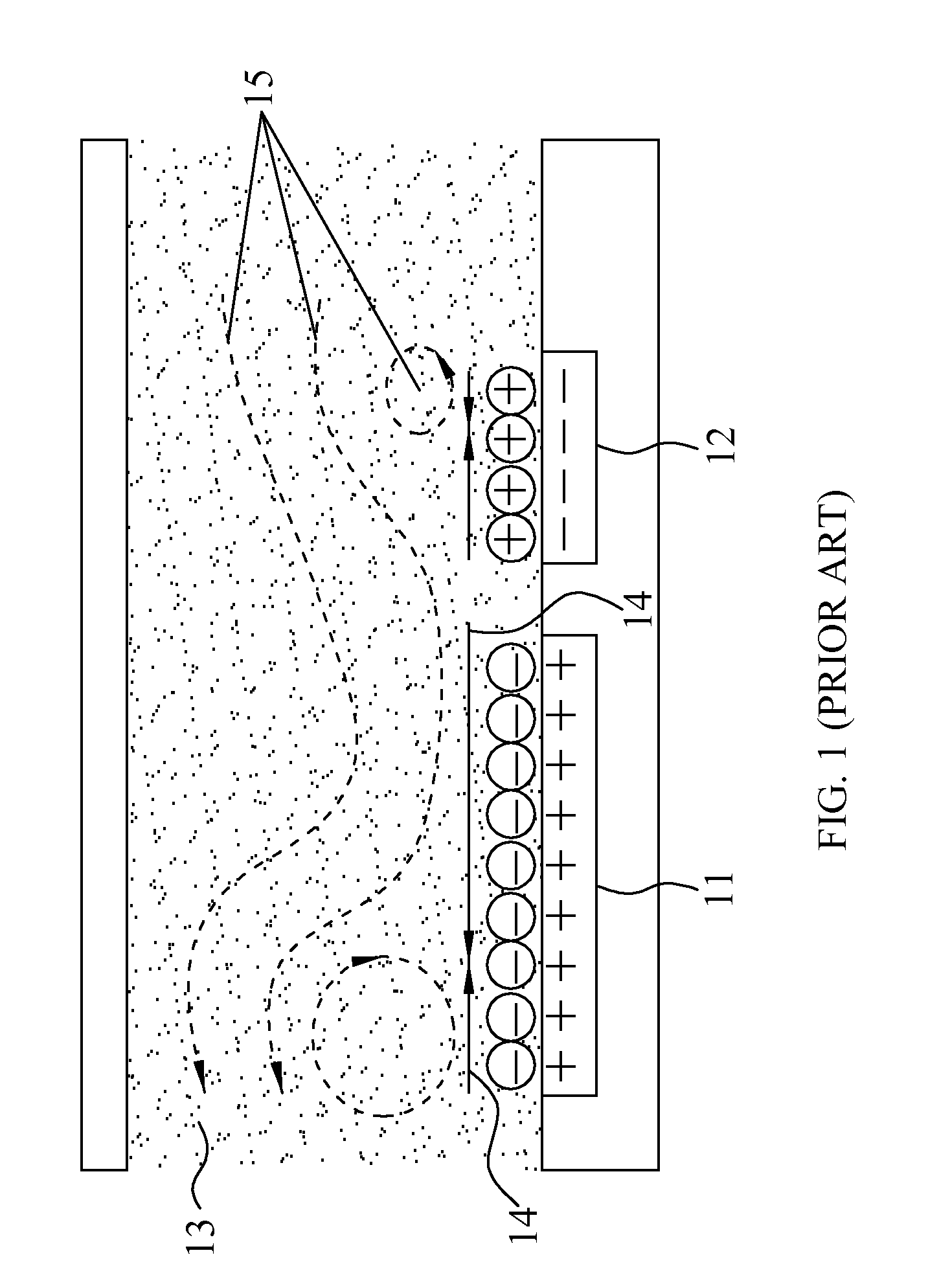
Image

Examples
first embodiment
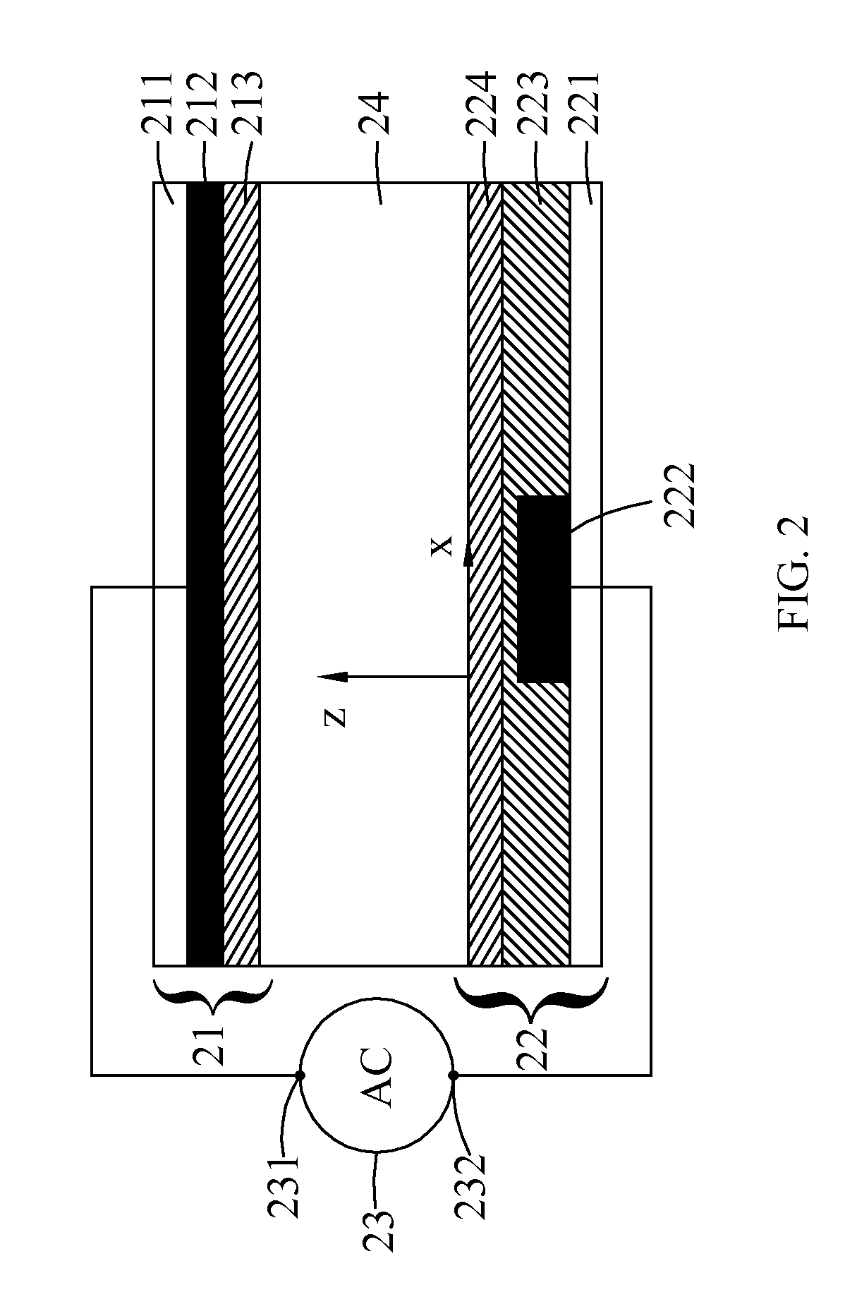
[0037]Please refer to FIG. 2. FIG. 2 is a diagram of a microfluidic driving system according to the present invention. As shown in FIG. 2, the microfluidic driving system includes a first planar electrode 21, a second planar electrode 22, and a power supply unit 23. The second planar electrode 22 is disposed parallel to the first planar electrode 21 and face-to-face with the first planar electrode 21 to form an accommodation space 24.
[0038]The first planar electrode 21 may include a first substrate 211, a first conductive layer 212, and a first hydrophobic film 213. The first substrate 211 may be a glass substrate, the first conductive layer 212 may be an ITO layer, and the first hydrophobic film 213 may be a Teflon film. Herein the ITO layer is disposed in one side of the glass substrate, and then the Teflon film is coated on the surface of the ITO layer to form the first planar electrode 21.
[0039]The second planar electrode 22 may include a second substrate 221, a second conductiv...
second embodiment
[0043]Please refer to FIG. 3A. FIG. 3A is a diagram of a microfluidic driving system according to the present invention. As shown in FIG. 3A, the shape of the first conductive layer 212 of the first planar electrode is a rectangle, the shape of the second conductive layer 222 of the second planar electrode is a rectangle with two protrusions (RWTP), and the area of the first conductive layer 212 is greater than the area of the second conductive layer 222, such that a non-uniform electric field may be produced by these two asymmetric conductive layers. In this embodiment, the RMS voltage of the AC power is 340 Vrms, and the frequency of the AC power is 140 KHz.
[0044]Please refer to FIG. 3B. FIG. 3B is a diagram illustrating a flow field of the microfluidic driving system according to a second embodiment of the present invention. The second conductive layer 222 is used as the datum plane (z=0 μm), and thus the relative position of the first conductive layer 212 is located at z=120 μm....
third embodiment
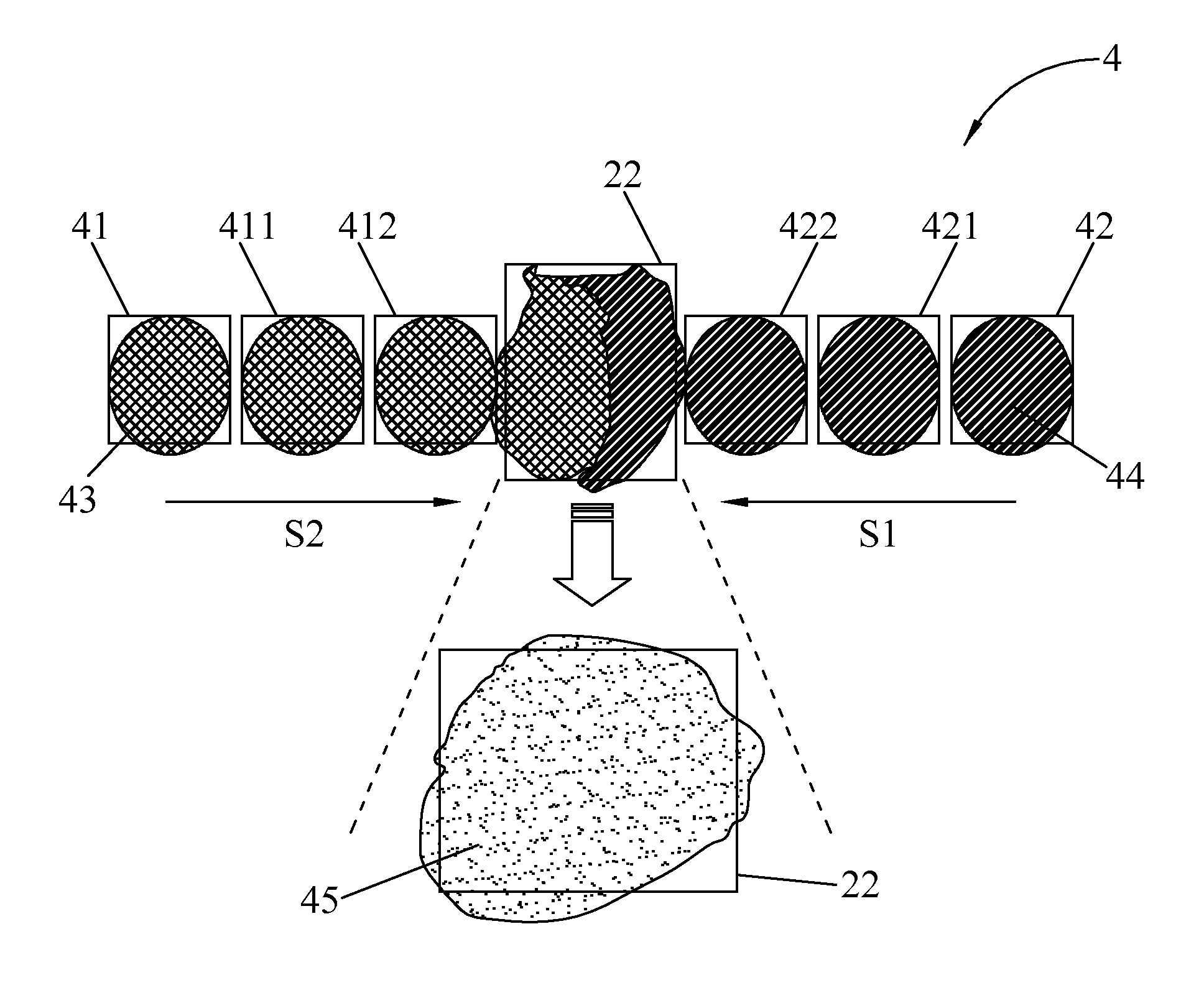
[0047]Please refer to FIG. 4A, which is a diagram of a microfluidic driving system according to the present invention. In FIG. 4A, the shape of the first conductive layer 212 is a rectangle, and the shape of the second conductive layer 222 is also a rectangle. Since the area of the first conductive layer 212 is greater than the area of the second conductive layer 222, non-uniform electric fields can be produced by means of these two asymmetric conductive layers. In this embodiment, the RMS voltage of the AC power is 340 Vrms, and the frequency of the AC power is 140 KHz.
[0048]Please refer to FIG. 4B, which is a diagram illustrating a flow field of the microfluidic driving system according to a third embodiment of the present invention. Compared with the abovementioned second embodiment, because the protruding part of the second conductive layer 222 vanishes, the effect for enhancing the vortexes by the partial electric field also vanishes, as is shown in FIG. 4B. The flow field flow...
PUM
| Property | Measurement | Unit |
|---|---|---|
| slip length | aaaaa | aaaaa |
| particle size | aaaaa | aaaaa |
| tangential velocity | aaaaa | aaaaa |
Abstract
Description
Claims
Application Information