Method of flip-chip hybridization for the forming of tight cavities and systems obtained by such a method

a technology of tight cavities and flip-chips, applied in the field of flip-chip hybridization, can solve the problems of inability to apply any type of hybridized components, and the inability to underfill according to the state of the ar

Inactive Publication Date: 2014-03-04
COMMISSARIAT A LENERGIE ATOMIQUE ET AUX ENERGIES ALTERNATIVES
View PDF10 Cites 0 Cited by
  • Summary
  • Abstract
  • Description
  • Claims
  • Application Information

AI Technical Summary

Benefits of technology

[0008]An object of the present invention is to provide a method for assembling two microelectronic components, which enables both to perform an underfilling operation and to create tight cavities embedded in the filling material used for the underfilling.
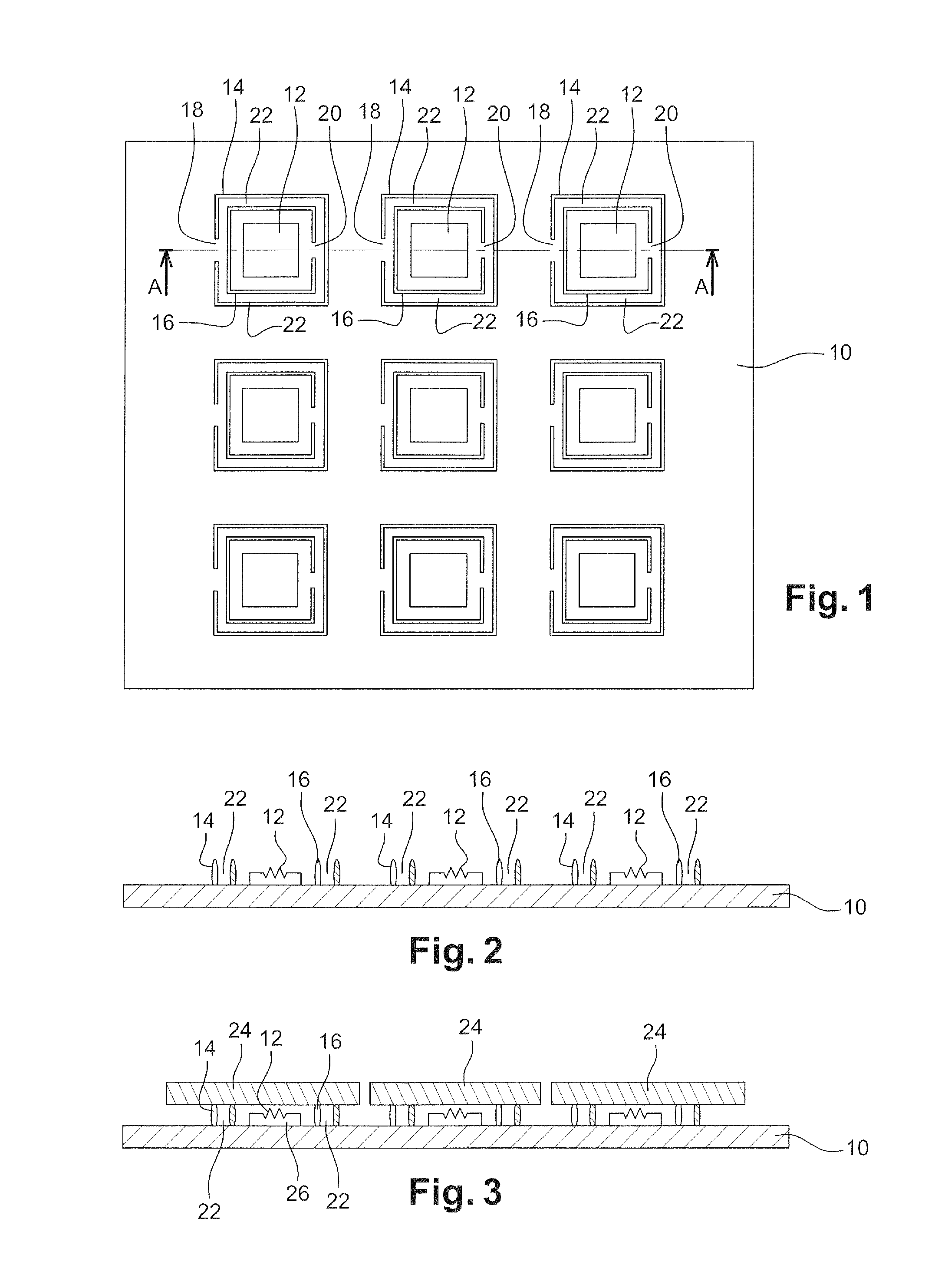
[0019]its first function, in combination with the vent, is to let the cavity communicate with the outside during the flip-chip hybridization operation. In the absence of such a communication, that is, if the lateral wall defining the cavity is entirely closed, and thus deprived of any vent, and if the flip-chip hybridization is not performed in vacuum, the installing of the second component on the first component may cause an overpressure in the cavity, which would mechanically weaken the hybridized assembly and / or would adversely affect the operation of certain circuits such as bolometric detectors and MEMS-based circuits. Further, during certain flip-chip hybridizations, a deoxidation flow is used to guarantee the quality of the electric interconnects, which requires being able to carry off acid gas releases in the cavity once the interconnects have been formed, and thus having access to the cavities.
[0020]the second function is to prevent the penetration of the filling material into the cavities. Indeed, a bypass duct lengthens the travel of the filling material between the vent and the inside of the cavity, which thus gives time for said material to solidify due to the flow time of the liquid material in the duct. It should besides be noted that the underfilling operation usually requires materials of low viscosity to obtain a satisfactory filling of the space separating the two hybridized components. In the absence of a bypass, the filling material in liquid form thus penetrates inside the cavity before it can be stopped by solidification.
[0028]According to another specific embodiment, the external and internal lateral walls associated with each of at least part or all of the cavities form an assembly of at least two frames nested around the cavity and closed, except for one vent per frame, the vent of a frame being arranged opposite to the vent of the closest frame containing it. This arrangement enables to decrease the surface area taken up by the bypass, while having lateral walls defining a substantially symmetrical assembly on the cavity circumference, thus implying that the stress exerted thereon is symmetrical and exerted uniformly during a thermal cycle.
[0030]According to an embodiment of the present invention, the filling material in liquid form is a polymer cross-linkable, for example, by heating or irradiation, the solidification being performed by cross-linking of said polymer. In particular, for a polymer cross-linkable by irradiation, for example, with UVs, the solidification is thus very fast and enables to controllably stop the progress of the filling material by increasing the fluence of the UV radiation. Similarly, for a polymer cross-linkable by heating, it is possible to controllably stop the progress if a temperature greater than the minimum polymer cross-linking temperature is applied, for example, a temperature greater than 100° C. for 15 minutes for an epoxy resin.
[0032]According to an embodiment of the present invention, the length of the bypass ducts is determined according to the flow speed of the filling material in liquid form. This especially enables to minimize the length of the bypass duct, and thus to decrease the surface area granted to each cavity and decrease the quantity of material dedicated to the forming of the lateral walls.

Problems solved by technology

Although the filling material has many advantages, it cannot be applied to any type of hybridized component.
In such cases, the underfilling operation according to the state of the art is then impossible, since it implies embedding said circuits.

Method used


Image

  • Method of flip-chip hybridization for the forming of tight cavities and systems obtained by such a method
  • Method of flip-chip hybridization for the forming of tight cavities and systems obtained by such a method
  • Method of flip-chip hybridization for the forming of tight cavities and systems obtained by such a method

Examples


Embodiment Construction

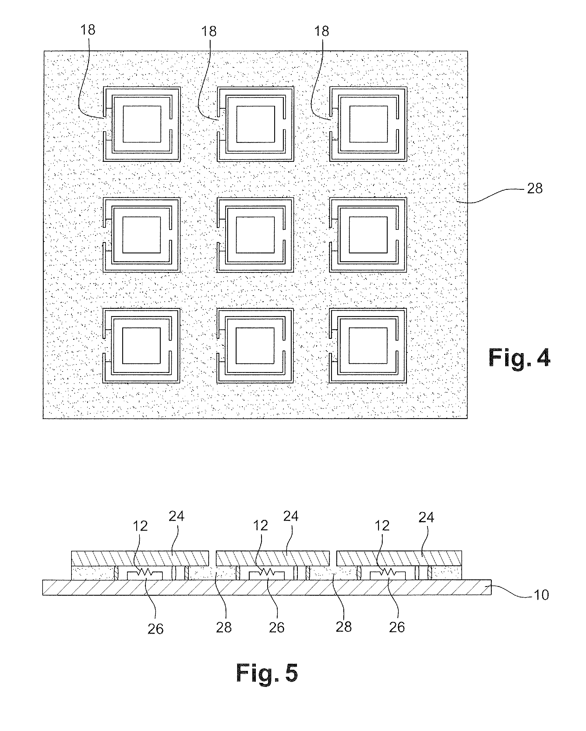
[0044]Referring to FIGS. 1 to 6, a method of an embodiment of the present invention applied to the collective forming of MEMS circuits, for example, an array of three by three MEMS circuits in the drawings, will now be described.

[0045]A circuit based on MEMSs for example comprises a substrate 10 on which or above which are formed MEMSs 12. For their operation, MEMSs 12 require being placed under low pressure, in vacuum, or under a controlled atmosphere. To achieve this, the MEMS circuits are enclosed in a tight cavity. MEMS circuits are well known per se and will not be described any further hereinafter. It should only be reminded that it is needed to provide tight cavities coated with a filling material in an underfilling operation.

[0046]As shown in FIGS. 1 and 2, the method starts with the forming of lateral walls 14, 16 around each MEMS circuit 12 to form:[0047]an external frame 14 closed except for a first vent 18; and[0048]a frame 16, internal to external frame 14, closed excep...


PUM


Abstract

A method for manufacturing a microelectronic assembly including stacked first and second microelectronic components having a cavity therebetween including defining said cavity by means of a lateral wall forming a closed frame extending around a determined area of the first component except for an opening used as a vent; forming within the closed frame and opposite to the vent an obstacle capable of forming, in cooperation with the lateral wall, a bypass duct for the filling material; performing a flip-chip hybridization of the first and second components, a surface of the second component resting on the upper edge or end of the lateral wall formed on the first component to form said at least one cavity; injecting the filling material in liquid form between the two hybridized components to embed said at least one cavity and to make it tight by obstruction of the vent as said filling material solidifies.

Description

FIELD OF THE INVENTION[0001]The present disclosure relates to the connection of two components according to the flip-chip hybridization technique.[0002]The present invention thus particularly applies to so-called “chip-on-chip”, “chip-on-wafer”, and “wafer-on-wafer” assemblies.BACKGROUND OF THE INVENTION[0003]Flip-chip hybridization is currently used to assemble two microelectronic components manufactured independently from each other, but operating complementarily, such as for example an array of unit detection elements and its read circuit, more generally by forming electromechanical connections with solder bumps or by insertion of hard metal inserts in ductile metal pads.[0004]Such hybridization is often completed by the filling of the space between the two hybridized components with a protection material, usually an epoxy resin, this operation being called underfilling.[0005]The filling material indeed enables to absorb thermal expansion differences between the first and second ...

Claims


Application Information

Patent Timeline
Patent Type & Authority Patents(United States)
IPC IPC(8): H01L23/28
CPCB81C2203/0145H01L21/563H01L23/24B81C1/00293H01L23/3128B81C2203/0118H01L2224/73203H01L21/56H01L23/3121H01L23/053H01L2924/12044H01L23/043H01L2924/1461H01L2924/00
Inventor MARION, FRANCOIS
Owner COMMISSARIAT A LENERGIE ATOMIQUE ET AUX ENERGIES ALTERNATIVES
Why Eureka
Try Eureka