
Efficient parallel sub-packet decoding using multiple decoders

a decoder and sub-packet technology, applied in the field of communication system decoding, can solve the problem of not being able to interrupt the processor frequently, and achieve the effect of reducing the number of decoders

Inactive Publication Date: 2014-03-04
QUALCOMM INC
View PDF18 Cites 4 Cited by
  • Summary
  • Abstract
  • Description
  • Claims
  • Application Information

AI Technical Summary

Problems solved by technology

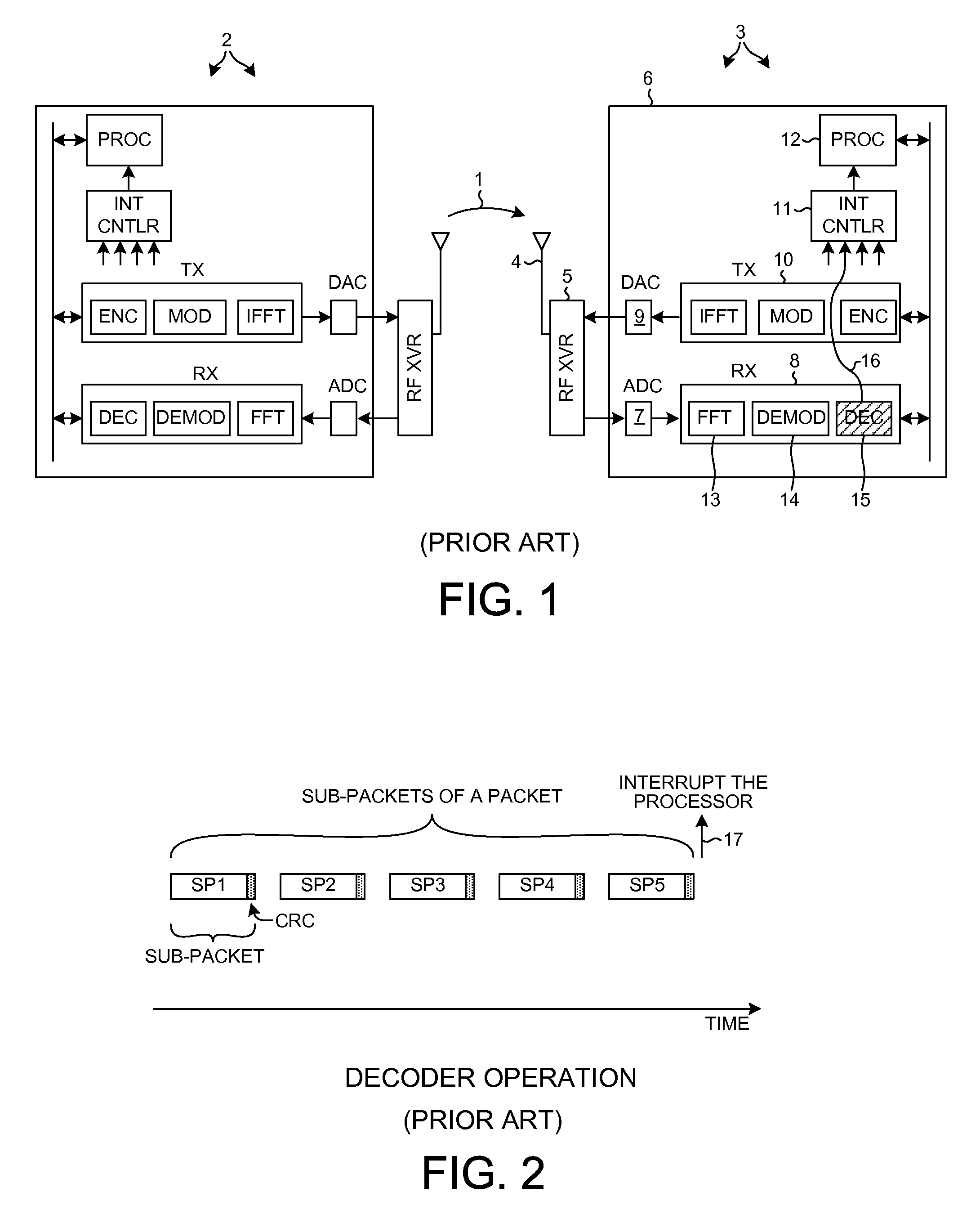
It is generally not desirable to interrupt the processor frequently because interrupting the processor slows the processor from performing other tasks.
Supporting such higher data throughput rates has burdened the processing capabilities of various portions of the circuits of wireless communication devices such as devices 2 and 3.

Method used


Image

  • Efficient parallel sub-packet decoding using multiple decoders
  • Efficient parallel sub-packet decoding using multiple decoders
  • Efficient parallel sub-packet decoding using multiple decoders

Examples


Embodiment Construction

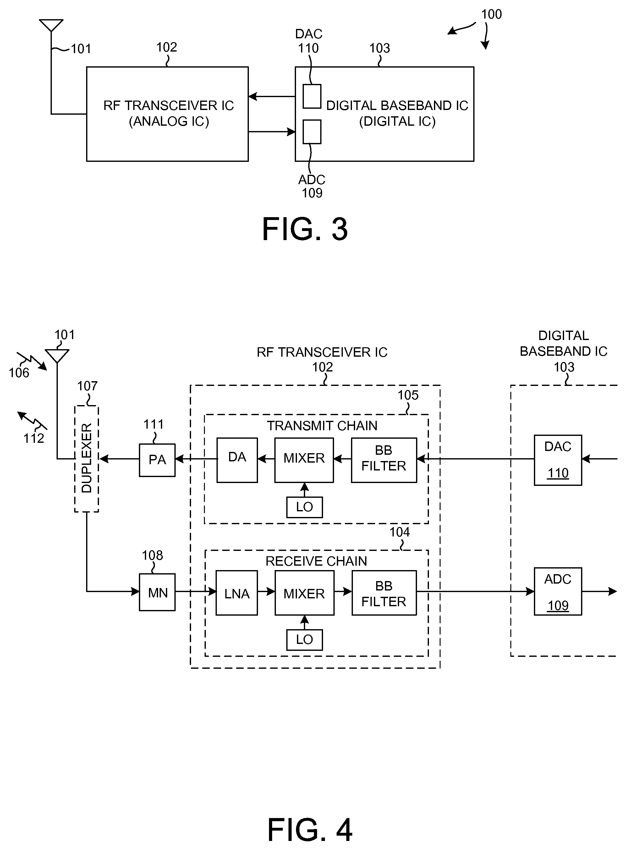
[0025]FIG. 3 is a simplified high level block diagram of an example of a wireless communication device 100. Wireless communication device 100 includes, among other parts not illustrated, an antenna 101, a Radio Frequency (RF) integrated circuit 102, and a digital baseband integrated circuit 103.

[0026]FIG. 4 is a more detailed block diagram of the antenna 101 and the RF transceiver integrated circuit 102 of FIG. 3. The RF transceiver integrated circuit 102 includes a receive chain 104 and a transmit chain 105. An incoming transmission 106 is received on antenna 101, and passes through a duplexer 107 and a matching network 108 and into the receive chain 104. After being downconverted in frequency in receive chain 104, the received signal passes to an Analog-to-Digital Converter (ADC) 109 in the digital baseband integrated circuit 103 for further processing. If wireless communication device 100 is to make a transmission, then digital information is converted into analog form by a Digit...


PUM


Abstract

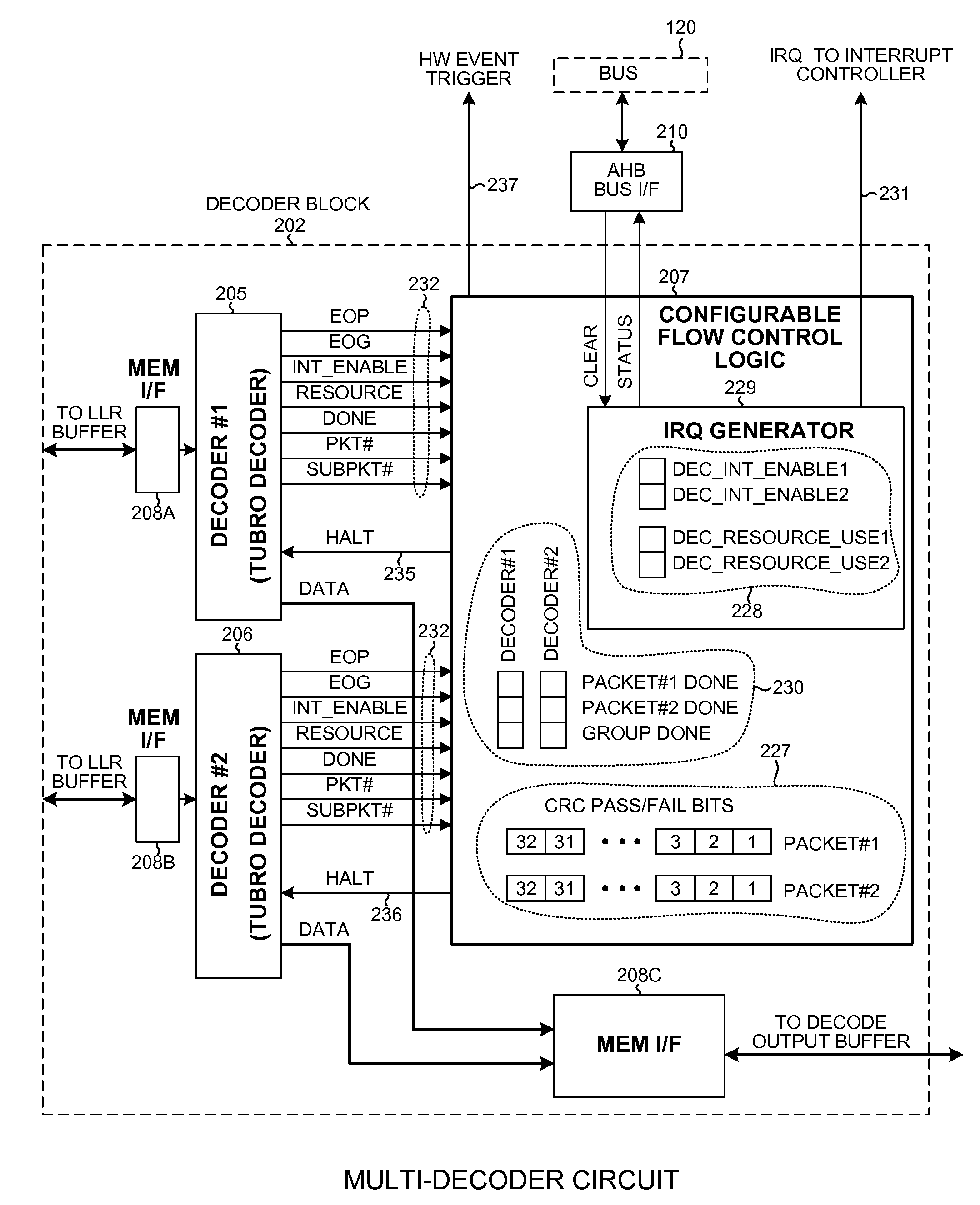
A configurable decoder within a receiver (for example, within a wireless communication device) includes numerous decoders. In one mode, the multiple decoders are used to decode different sub-packets of a packet. When one decoder completes decoding the last sub-packet assigned to it of the packet, then that decoder generates a packet done indication. A control circuit receives the packet done indications, and when all the decoders have generated packet done indications then the control circuit initiates an action. In one example, the action is the interrupting of a processor. The processor responds by reading status information from the control circuit, thereby resetting the interrupt. End-of-packet markers are usable to generate packet done indications and to generate EOP interrupts. Similarly, end-of-group markers are usable to generate group done indications and to generate EOG interrupts. The decoder block is configurable to process sub-packets of a packet using either one or multiple decoders.

Description

CROSS-REFERENCE TO RELATED APPLICATION[0001]This application claims the benefit under 35 U.S.C. §119 of Provisional Application Ser. No. 61 / 041,558, filed Apr. 1, 2008, said provisional application is incorporated herein by reference.BACKGROUND INFORMATION[0002]1. Technical Field[0003]The present disclosure relates to decoding in communication systems.[0004]2. Background Information[0005]FIG. 1 (Prior Art) is a diagram of one type of conventional wireless communication system that communicates packets. Packets 1 of data can be communicated from a first wireless communication device 2 to a second wireless communication device 3. Communication device 3 includes an antenna 4, a RF transceiver integrated circuit 5, and a digital baseband integrated circuit 6. Digital baseband integrated circuit 6 includes a number of parts including an Analog-to-Digital Converter (ADC) 7, a receive path 8, a Digital-to-Analog Converter (DAC) 9, a transmit path 10, an interrupt controller mechanism 11, a...

Claims


Application Information

Patent Timeline
Patent Type & Authority Patents(United States)
IPC IPC(8): H04L27/06
CPCH03M13/6561H04L1/0045H03M13/6508H03M13/41H04L1/0052H03M13/2957
Inventor ZANOTELLI, JOSEPHNATH, MRINAL MAHESHCHAUDHURI, ARUNAVAGHOSH, KAUSHIKCHALLA, RAGHUJING, WEIHONG
Owner QUALCOMM INC
Learn More