Actuator for a closing element of a valve

a technology of actuator and closing element, which is applied in the direction of valve operating means/release devices, machines/engines, etc., can solve the problems of high wear risk also in the mouth region of the guide, and the number of actuator parts is inappropriately increased, and the material of the known actuator is extremely tough and expensive, so as to achieve easy manufacturability

Active Publication Date: 2014-03-11
KRONES AG
View PDF30 Cites 7 Cited by
  • Summary
  • Abstract
  • Description
  • Claims
  • Application Information

AI Technical Summary

Benefits of technology

[0006]One aspect underlying the disclosure is to provide an actuator of the type mentioned in the beginning which is very fail-safe, structurally simple and nevertheless inexpensive.
[0007]As the end of the one guide rod is anchored in one cover and the end of the other guide rod is anchored in the other cover of the housing, the free effective bending length of a guide rod is a minimum in each end position of the piston, so that the bending loads and bending stresses of this guide rod are also minimal. while its guide length simultaneously is a maximum, so that the specific surface pressure between the guide and the guide rod remains low, even if the reaction moment to be transmitted then is a maximum. The guide rod whose free effective bending length is a minimum thus relieves the other guide rod of the load, whose free effective bending length then is a maximum. This altogether reduces the bending loads and bending stresses for the two guide rods, and this in the anchoring regions as well as in the mouths of the guides. This is accompanied by a reduction in wear of the guide rods in the guides. Though in the stroke motion of the piston from the respective end position, the free effective bending length of the guide rod whose free effective bending length initially was a minimum increases, the free effective bending length of the other guide rod is at the same time reduced, so that the reaction torque is transmitted without problems over the stroke distance of the piston while the bending stresses are reduced for both guide rods. The anchoring regions, e.g. welding regions, are less loaded, reducing the risk of damages and simultaneously sensibly increasing operational and process reliability, respectively. Due to the lower bending loads of the guide rods, the latter can be made of an inexpensive material, optionally of the same material as the covers. This facilitates anchorage, for example by welding. The actuator only consists of a small number of parts and can be inexpensively manufactured, as the manufacture of the anchorage region, for example, can be automated and the guide rods possibly do not require any readjustment. As in both stroke end positions of the piston, the respective reaction torque is particularly stably introduced into the housing, the values and characteristics of the torques which then must be transmitted from the actuator to the function element, e.g. the closing element of a disk valve, can be very precisely predetermined and adjusted to the switching behavior of the disk valve, for example such that the preferably plateau-like maxima of these torques are at the stroke end positions of the piston.
[0009]It is advantageous for the maximal free effective bending length of the one guide rod in a respective piston end position in the housing to correspond to between approximately half to two thirds of the piston's outer diameter and / or approximately twice the overlap of the free ends of the two guide rods. This relatively short free effective bending length reduces the bending loads of this guide rod to a moderate degree, which is anyway supported by the other guide rod which can then very stably accept loads with a minimum free effective bending length.
[0018]Advantageously, each cover has one single mounting for a guide rod end. The guide rod is anchored with its end in the mounting by welding, screwing, shrinking, gluing or calking. Anchorage can be produced in an automated operating sequence, and thereby with high precision, so that readjustment of the anchored guide rods becomes dispensable.
[0019]Particularly advantageously, inexpensively and optimally in view of the quality of the anchorage, the guide rod is anchored with its end in the mounting of the cover by friction welding, preferably automated friction welding. The friction welding operation results in a nearly monolithic anchorage and permits to implement exact positioning and alignment of the guide rod in the cover during friction welding, so that readjustment of the guide rod can be eliminated.
[0021]With respect to easy manufacturability, it can be advantageous to use as guide rods circular cylindrical solid material rods, and to design the guides as blind holes in the piston. This should, however, not exclude to use also hollow profiles or tubes as guide rods, and to place the latter onto pins provided at the covers and anchor them e.g. by friction welding.

Problems solved by technology

As, depending on the construction and function of the valve controlled by the actuator, one cannot exclude that the reaction torque at the piston is highest when the free effective bending lengths at both guide rods are longest, the risk of wear in the region of the anchorages and also in the mouth regions of the guides and there at the guide rods is high.
To allow for this situation, the guide rods are furthermore made of an extremely tough and expensive material in the known actuator.
In addition, the piston skirt is reinforced by a metallic outer supporting tube, whereby the number of parts of the actuator is inappropriately increased.
As furthermore the cover in which the two guide rods are anchored is not made of the same expensive material as the guide rods themselves for financial reasons. welding of two different materials is problematic, possibly such that no automated welding procedure can be carried out.
Nevertheless, the risk of a rupture in the respective welding point remains acute, and this simultaneously in both guide rods as both guide rods are anchored in the same cover and are simultaneously subjected to the highest bending forces when their free effective bending lengths increase together during the operation of the actuator.
The four guide rods which radially have the same distances from the piston axis, which are situated diametrically opposed to each other in pairs each, where one guide rod of one pair each is placed relatively close adjacent to a guide rod of the other pair in the circumferential direction, furthermore inappropriately restrict the radian measure in the piston skirt usable for the connecting links.
The actuator consists of many parts, mainly due to the four guide rods, and requires time and cost consuming manufacture.

Method used


Image

  • Actuator for a closing element of a valve
  • Actuator for a closing element of a valve
  • Actuator for a closing element of a valve

Examples


Embodiment Construction

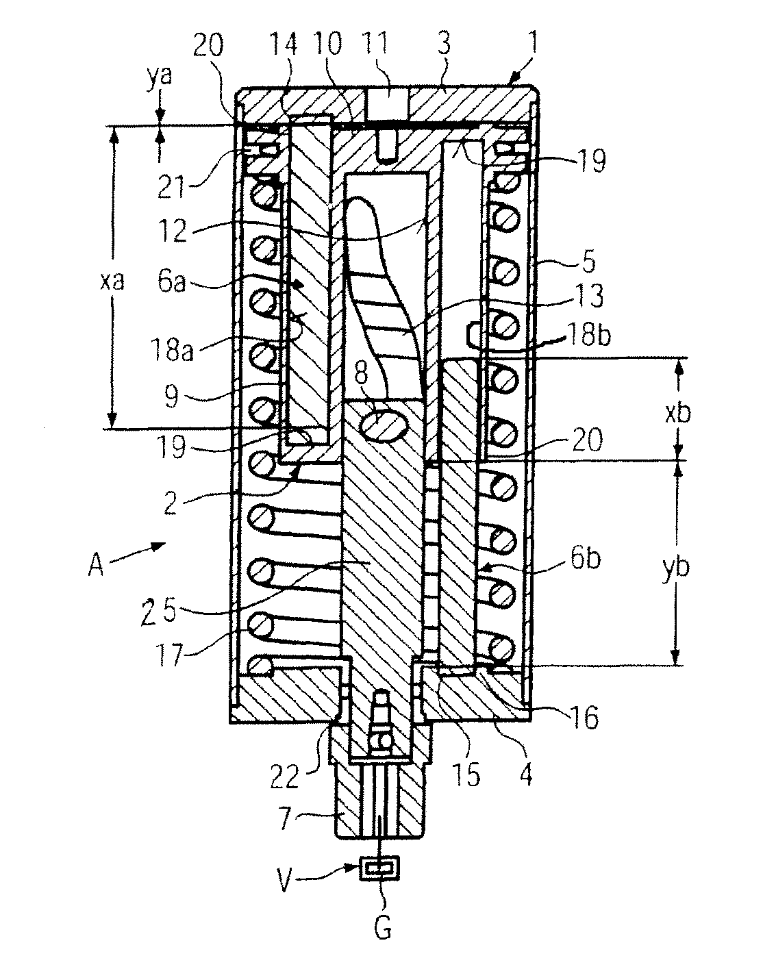
[0026]The actuator A is used, for example, for adjusting a rotary function element G by rotation. for example a closing element of a disk valve V or a ball valve, for example in the beverage bottling industry, w here the function element G requires a certain torque and progression of the torque for rotary adjustment by a certain angle of rotation (e.g. 90°) which the actuator A produces and applies. The required switching torque can be a maximum for example during the movement of the function element G into or out of an end position. In the embodiment in FIG. 1, the actuator is operated by a pressure means, for example by means of compressed air, and this in a direction of stroke against a readjusting spring, however, it could also be subjected to the pressure means from both sides, or be driven by another drive element that produces a linear motion, and generates the rotary motion for the function element G from the linear drive motion. During the actuation of the actuator A in a d...


PUM


Abstract

An actuator for a rotary function element, having a housing with at least one pressure means supply and being closed at both sides by a cover, in which housing a piston is guided to reciprocate in a sealing manner, the piston containing diametrically opposed, convolution-like connecting links for a transverse axis of an actuator shaft rotatably mounted in one cover, and having two guide rods firmly anchored in the housing only at one end and engaging into guides in the piston, with the one guide rod anchored in one cover, whereas the other guide rod is anchored in the other cover, and the two guides end blind in the piston in opposite directions.

Description

CROSS-REFERENCE TO RELATED APPLICATION[0001]The present application claims the benefit of priority of German Application No. 102010002621.2, filed Mar. 5, 2010. The entire text of the priority application is incorporated herein by reference in its entirety.FIELD OF THE DISCLOSURE[0002]The disclosure relates to an actuator used for a rotary function element.BACKGROUND[0003]A preferred, though not restricting, field of application of such actuators is e.g. disk valves or ball cocks in the beverage bottling industry. In such disk valves or ball cocks, in at least one end position or in movements of the closing element into or out of the end position, a very high or the maximum switching torque must be often generated by the actuator, which can be subjected to pressure means, e.g. compressed air, on one side against a spring force, or on both sides.[0004]In the generic actuator known from EP 1 222 403 A, both guide rods are loaded by the piston simultaneously and in the same manner to t...

Claims


Application Information

Patent Timeline
Patent Type & Authority Patents(United States)
IPC IPC(8): F15B15/06
CPCF15B15/068Y10T74/18296
Inventor WIEDENMANN, WILLIMANNL, STEPHANSAUER, MARTIN
Owner KRONES AG
Why Eureka
Try Eureka