Method for protecting a touch-screen display

Inactive Publication Date: 2014-03-18
RAISCH NETANEL
View PDF6 Cites 17 Cited by
  • Summary
  • Abstract
  • Description
  • Claims
  • Application Information

AI Technical Summary

Benefits of technology

[0033]In another aspect of the device, the magnetic elements are selected for size, material and appearance so as to allow for easy viewing of the display screen.
[0034]The invention includes a method for protecting a touch-screen display from physical damage, including: providing an optically clear solid element whose dimensions are similar to those of the display and whose thickness is selected to prevent damage to the display; disposing magnet pairs on either side of the solid element, wherein the

Problems solved by technology

One of the challenges of touch-sensitive screens has been their relative fragility.
If the screen is covered with a thick cover, then the display is safe from damage but the computerized devices are for all purposes unusable.
If the screen is available for user access, then the risk

Method used


Image

  • Method for protecting a touch-screen display
  • Method for protecting a touch-screen display
  • Method for protecting a touch-screen display

Examples


first embodiment

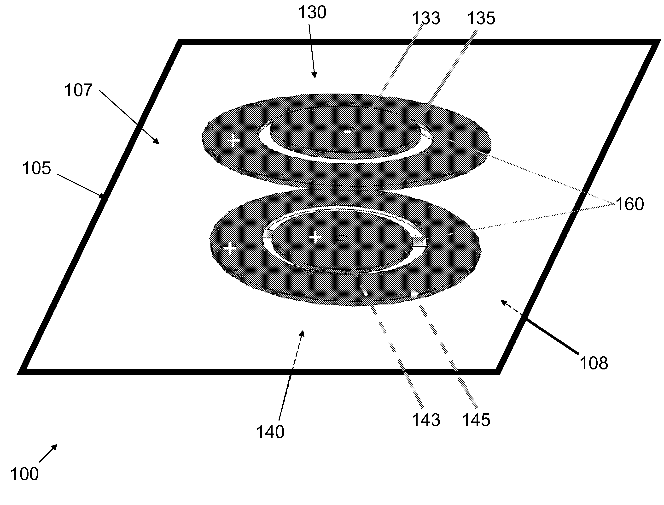
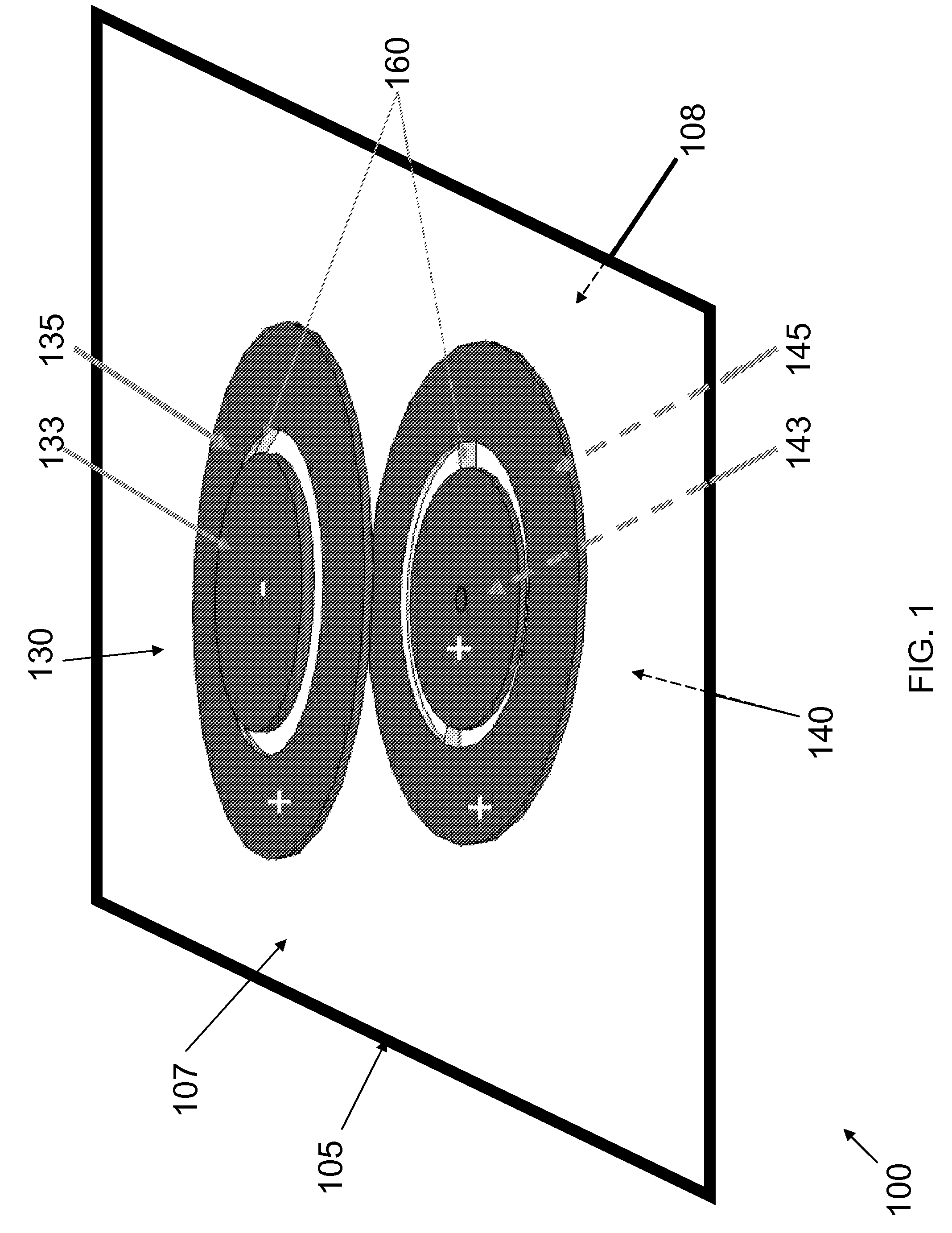
[0053]Attention is turned to FIG. 1 which shows a schematic view of an embodiment of a touch-sensitive screen protector 100. A rigid, generally flat optically clear element 105 has an outer surface 107 and an inner surface 108. The inner surface 108 is generally the side of the element 105 which is closest to a touch-sensitive or similar display (not shown) and furthest from a user (not shown) of a device that includes the aforementioned display. In this embodiment, a first magnet pair 130 is disposed on the outer side 107 of the element 105, while a second magnet pair 140 is disposed on the inner side 108 of the element 105. Each magnet pair 130&140 includes at least two magnets: the outer magnet pair 130 includes magnets 133&135, while the inner magnet pair 140 includes magnets 143&145. The magnets in the drawings are circular magnets, the circle shape being just an option and the magnets may be of any relevant shape, size or composition. In a typical embodiment, magnets 133, 135&...

second embodiment '

Second Embodiment'

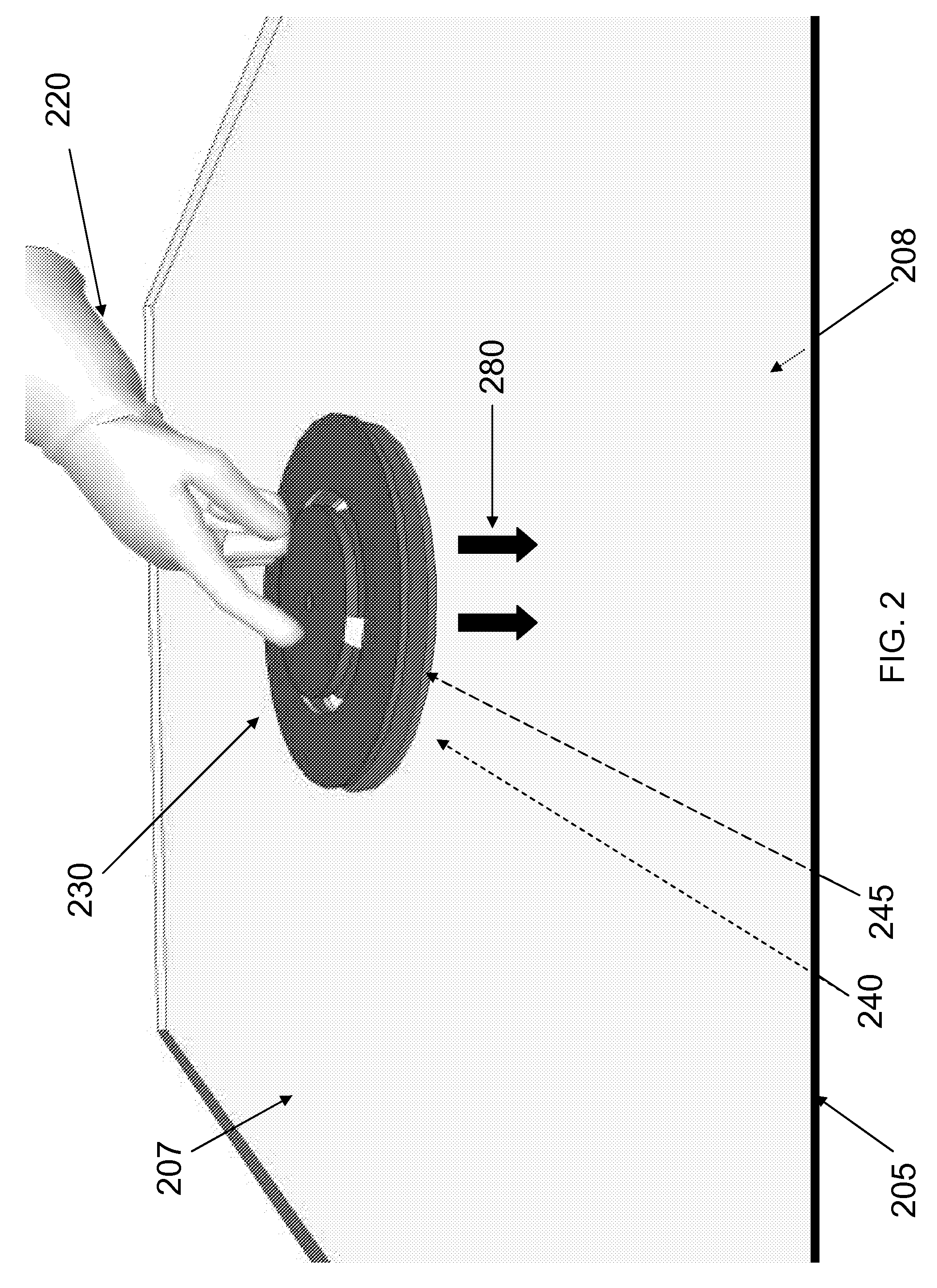
[0057]Attention is now turned to FIG. 5 which shows a schematic view of an embodiment of the instant invention. A touch-sensitive display 515 associated with a cellular phone, tablet computer, watch, handheld electronic device or the like is covered with an element 505 which is impact resistant. Holding features 518 may be used to fasten the element to the display 515 so as to leave space 580 between element 505 and display 515. Such features 518 include but are not limited to clips and contact elements. Contact elements may be any features that aid in attaching the element 505 proximate the surface of the display 515. The impact resistant element 505 has an upper magnet pair 530 and a lower magnet pair 540. The upper magnet pair 530 is shown slightly displaced above the element, though—as described in the previous embodiment—only one of the two magnets of the magnet pair 530 is generally displaced from the element 505 surface. A stylus 538 capable of activating th...

third embodiment

[0060]Attention is now turned to FIG. 7 which describes a method for protecting a touch-screen display from physical damage, including: providing an optically clear solid element whose dimensions are similar to those of the display and whose thickness is selected to prevent damage to the display; disposing magnet pairs on either side of the solid element, wherein the magnet pairs are disposed opposite one another and wherein physical contact with one magnet of a first magnet pair causes magnetic repulsion of a first magnet opposite it in the second magnet pair on the other side of the solid element; associating a stylus to the first magnet of the second magnet pair, wherein the stylus is disposed away from the solid element; and, securing the solid element with the magnets and stylus onto the display, wherein the stylus is in non-contact proximity to the display. The method herewith described allows a user to interact with a touch-sensitive display through the medium of a optically-...


PUM

PropertyMeasurementUnit
Thicknessaaaaaaaaaa
Frictionaaaaaaaaaa

Abstract

The invention discloses methods for transferring a tactile signal through an inert piece of material. In some embodiments, clear, impact resistant covers are employed with devices including touch-sensitive screens. The instant invention, in some embodiments, describes a method for employing a plurality of magnets to allow a user to input information on a touch-sensitive screen through the inert cover. Contact of a magnet pair above the cover may allow for a signal to be delivered to the touch-sensitive display via a second magnet pair that includes a stylus adapted to activate the surface of the display.

Description

FIELD AND BACKGROUND OF THE INVENTION[0001]The present invention, in some embodiments thereof, relates to methods and devices for allowing the transfer of a tactile signal through a solid, non-conducting surface. The instant invention, in some embodiments, allows for a user to access a touch-screen display through a rigid, otherwise electrically unresponsive cover.[0002]One of the greatest revolutions in the electronics sphere has been devices with touch-sensitive displays. “Smart” phones, tablet computers, GPS devices and other advanced devices allow for a touch-based interface between a user and the device. A typical smart phone allows one to access Internet, email, phone, pictures, music, applications, and a host of other features through finger-based actions on a touch-sensitive screen.[0003]One of the challenges of touch-sensitive screens has been their relative fragility. A veritable cottage industry exists for replacing and fixing cracked screens associated with phones and ta...

Claims


Application Information

Patent Timeline
IPC IPC(8): H01F7/06
CPCG06F3/017H01F7/0242G06F3/00G06F3/039Y10T29/49135Y10T29/49155Y10T29/49169Y10T29/49128Y10T29/49904H01F7/06Y10T29/4902G06F3/0393
Inventor RAISCH, NETANEL
Owner RAISCH NETANEL
Why Eureka
Try Eureka