Exhaust gas purifying apparatus for internal combustion engine

a technology of exhaust gas purification apparatus and internal combustion engine, which is applied in mechanical equipment, machines/engines, electric control, etc., can solve the problems of insufficient fuel efficiency improvement, inability to suppress, and inability to greatly extend the engine operating region where lean operation is performed, so as to prevent the increase of nox emission amount, suppress nox emission amount, and improve fuel efficiency

Active Publication Date: 2014-03-18
HONDA MOTOR CO LTD
View PDF10 Cites 13 Cited by
  • Summary
  • Abstract
  • Description
  • Claims
  • Application Information

AI Technical Summary

Benefits of technology

[0012]The present invention is made contemplating the above-described points, and an objective of the present invention is to provide an exhaust gas purifying apparatus for an internal combustion engine, which can surely prevent the increase in the NOx emission amount due to the lean operation or the fuel cut operation, to sufficiently suppress the NOx emission amount as well as to improve fuel efficiency.

Problems solved by technology

Therefore, improvement in the fuel efficiency is insufficient due to suppressing the NOx emission amount.
As apparent from FIG. 23, even if using the method shown in JP'040, the increase in the NOx emission amount GNOxEX immediately after the end of the lean operation cannot be suppressed completely (FIG. 23D, t102-t104), which means that the engine operating region where the lean operation is performed cannot be greatly extended.
Further, the fuel efficiency is not greatly improved since the fuel efficiency decreases due to enrichment of the air-fuel ratio (FIG. 23B, t102-t104).
However, the NOx emission amount increases immediately after the end of the fuel cut operation, since a large amount of oxygen is stored in the three-way catalyst during the fuel cut operation.
Therefore, it is necessary to restrict the condition for performing the fuel cut operation, which raises a problem that the fuel efficiency cannot be sufficiently improved by the fuel cut operation.
However, according to this control method, there is a problem that the engine output torque greatly changes due to the rapid change in the air-fuel ratio, which consequently degrades drivability of the engine.

Method used


Image

  • Exhaust gas purifying apparatus for internal combustion engine
  • Exhaust gas purifying apparatus for internal combustion engine
  • Exhaust gas purifying apparatus for internal combustion engine

Examples


Embodiment Construction

[0065]Preferred embodiments of the present invention will now be described with reference to the drawings.

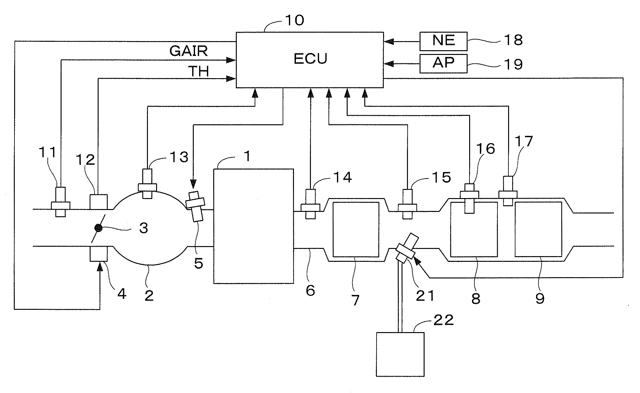
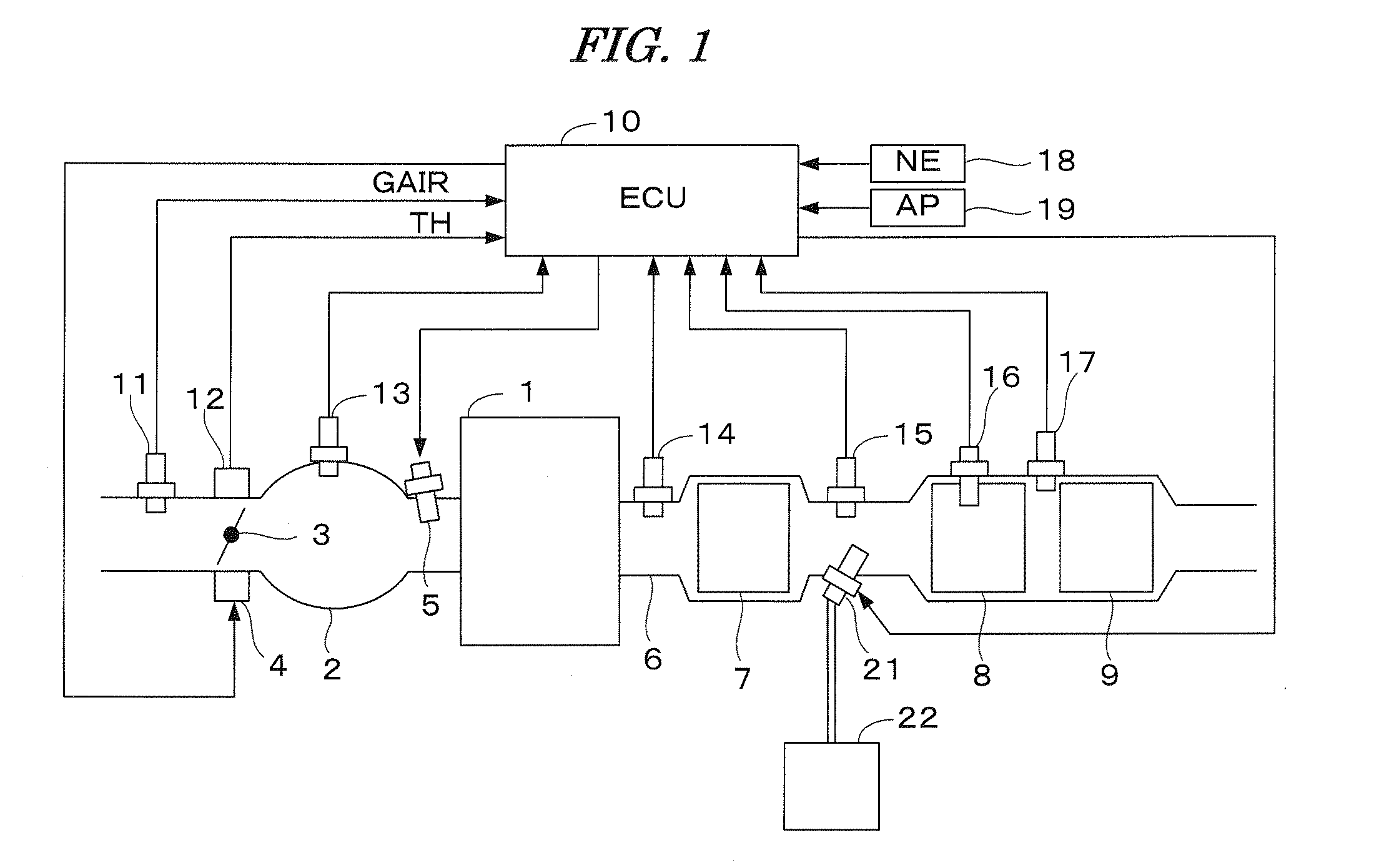
[0066]FIG. 1 is a schematic diagram showing a configuration of an internal combustion engine and a control system therefor according to an embodiment of the present invention. An internal combustion engine 1 (hereinafter referred to merely as “engine”) is a spark-ignition engine having, for example, four cylinders. The engine 1 has an intake pipe 2 provided with a throttle valve 3. An actuator 4 for actuating the throttle valve 3 is connected to the throttle valve 3, and the operation of the actuator 4 is controlled by an electronic control unit 10 (hereinafter referred to as “ECU”). The throttle valve 3 is provided with a throttle valve opening sensor 12 for detecting an opening TH of the throttle valve 3, and an intake air flow rate sensor 11 for detecting an intake air flow rate GAIR [g / sec] is disposed upstream of the throttle valve 3. The detection signals of these sensors ...


PUM


Abstract

An exhaust gas purifying apparatus for an internal combustion engine is provided. The apparatus includes a first catalyst and a second catalyst. The first catalyst is provided in an exhaust passage of the engine, and can remove NOx in exhaust gases from the engine when an air-fuel ratio of an air-fuel mixture burning in the engine is in the vicinity of the stoichiometric ratio. The second catalyst is provided downstream of the first catalyst, an can remove NOx in the exhaust gases using a reducing agent. An execution condition of a lean operation in which the air-fuel ratio is set to a lean air-fuel ratio which is leaner than the stoichiometric ratio, is determined. When switching the air-fuel ratio from an air-fuel ratio in the vicinity of the stoichiometric ratio to the lean air-fuel ratio, the air-fuel ratio is controlled to a rich air-fuel ratio which is richer than the stoichiometric ratio, during a lean transition period from the time the execution condition is satisfied. The air-fuel ratio is controlled to the lean air-fuel ratio after the lean transition period has elapsed.

Description

BACKGROUND OF THE INVENTION[0001]1. Field of the Invention[0002]The present invention relates to an exhaust gas purifying apparatus for an internal combustion engine, and particularly to the exhaust gas purifying apparatus having a three-way catalyst and a selective reducing catalyst disposed in the exhaust system of the engine.[0003]2. Description of the Related Art[0004]FIG. 21 show a configuration of a conventional well-known internal combustion engine and an exhaust gas purifying apparatus thereof. Three way catalysts 102 and 103, an air-fuel ratio sensor 104, and a binary-type oxygen concentration sensor (referred to as “O2 sensor”) are provided in an exhaust passage 101 of the internal combustion engine. In this apparatus, an air-fuel ratio feedback control is performed so that the air-fuel ratio detected by the air-fuel ratio sensor 104 coincides with a target air-fuel ratio. The three-way catalyst has a characteristic that the removing rates of carbon hydrate, carbon monoxid...

Claims


Application Information

Patent Timeline
Patent Type & Authority Patents(United States)
IPC IPC(8): F01N3/18F01N11/00
CPCF01N2610/02F01N13/02F01N2900/1402Y02T10/24F01N2560/025F01N2900/1622F02D41/0275F01N13/008F01N2013/026F01N2570/14F02D41/1475F01N3/208F01N2560/021F02D41/1441F02D41/0295F01N2013/023F02D2041/1468F01N2610/06F01N13/009F01N13/0097F01N13/0093Y02A50/20Y02T10/12F01N2900/1624
Inventor YASUI, YUJI
Owner HONDA MOTOR CO LTD
Why Eureka
Try Eureka