
Inkjet printing apparatus and calibration method

a printing apparatus and calibration method technology, applied in the field of calibration methods, can solve the problems that the calibration based on the measurement result does not reflect printing properties, and achieve the effect of reducing the effect of time reduction and small color differences

Active Publication Date: 2014-03-18
CANON KK
View PDF43 Cites 13 Cited by
  • Summary
  • Abstract
  • Description
  • Claims
  • Application Information

AI Technical Summary

Benefits of technology

This approach minimizes waiting time while ensuring color stability, allowing for precise calibration of printing properties by dynamically setting the waiting time according to the specific conditions of the ink type and amount used.

Problems solved by technology

As the result, calibration based on the measurement result does not reflect printing properties at that time.

Method used


Image

  • Inkjet printing apparatus and calibration method
  • Inkjet printing apparatus and calibration method
  • Inkjet printing apparatus and calibration method

Examples


first embodiment

[0037]A first embodiment of the present invention relates to a manner in which an image for calibration is printed with a primary color of each of the print heads 2C, 2M, 2Y and 2K, and a head control parameter corresponding to each of the print heads is set or changed on the basis of the measurement result of the image.

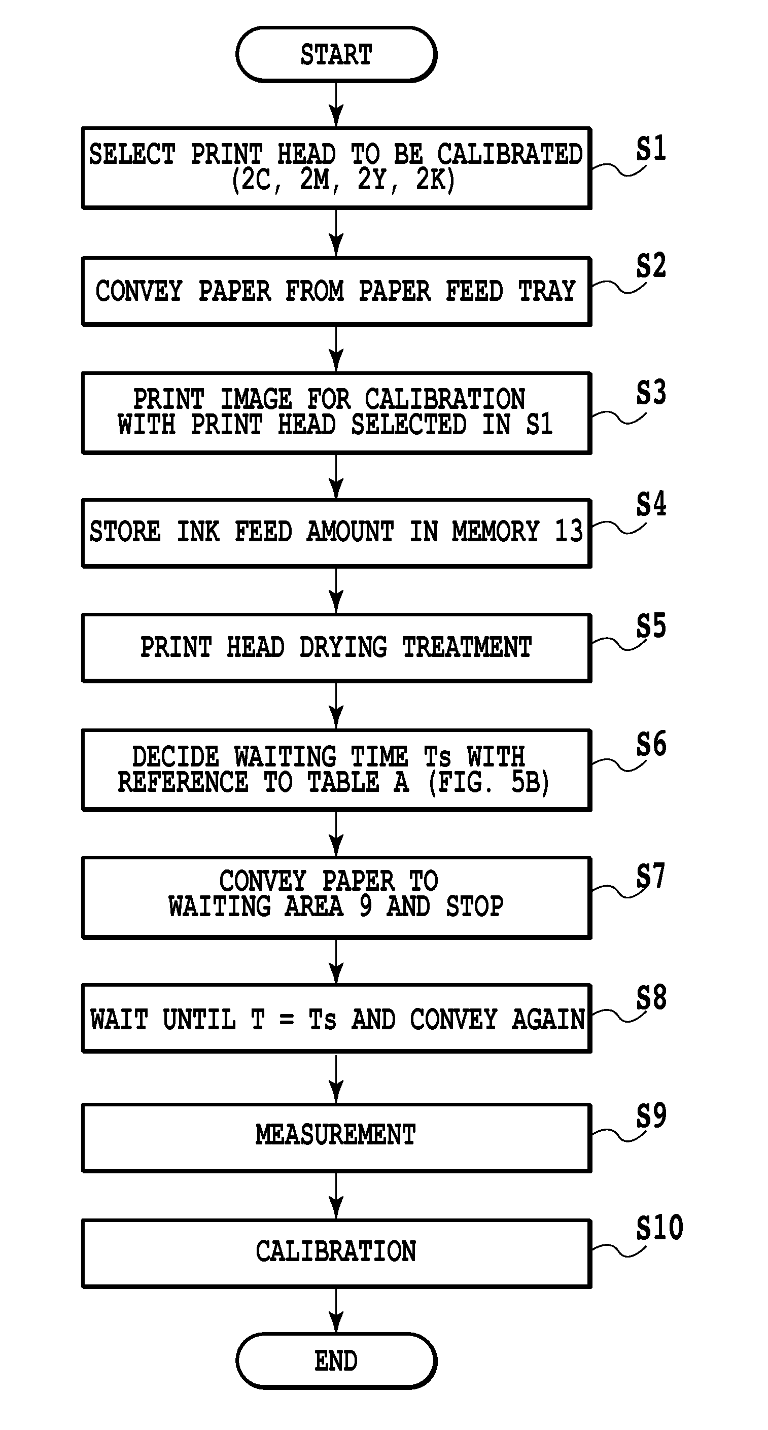
[0038]FIG. 4 is a flow chart illustrating a series of treatment and processing from printing an image for calibration to calibration based on the measurement result of the image, in calibration according to a first embodiment of the present invention. The treatment and processing in the case where calibration is performed for one print head 2C will be described below to simplify explanation.

[0039]In FIG. 4, first, a print head to be calibrated is selected (Step 1). Next, the printing paper 3 is fed from the paper feed tray 4 (Step 2). The fed printing paper 3 is carried by the conveying rollers 5 and an image for calibration of a primary color is printed on the print...

second embodiment

[0047]In the aforementioned first embodiment, one print head is calibrated in one calibration processing, but in the second embodiment of the present invention, a plurality of print heads are calibrated in one calibration processing. An example in which density properties of print heads 2C and 2Y are simultaneously calibrated will be described below.

[0048]FIG. 6A is a view of an image for calibration in the case where two print heads 2C and 2Y are simultaneously calibrated. As illustrated in FIG. 6A, by performing printing on a single printing paper with the print heads 2C and 2Y, a series of treatment and processing such as drying treatment and measurement after printing can be performed at one time. Here, a series of treatment and processing is the same as those of the aforementioned first embodiment, except for a decision method of a waiting time.

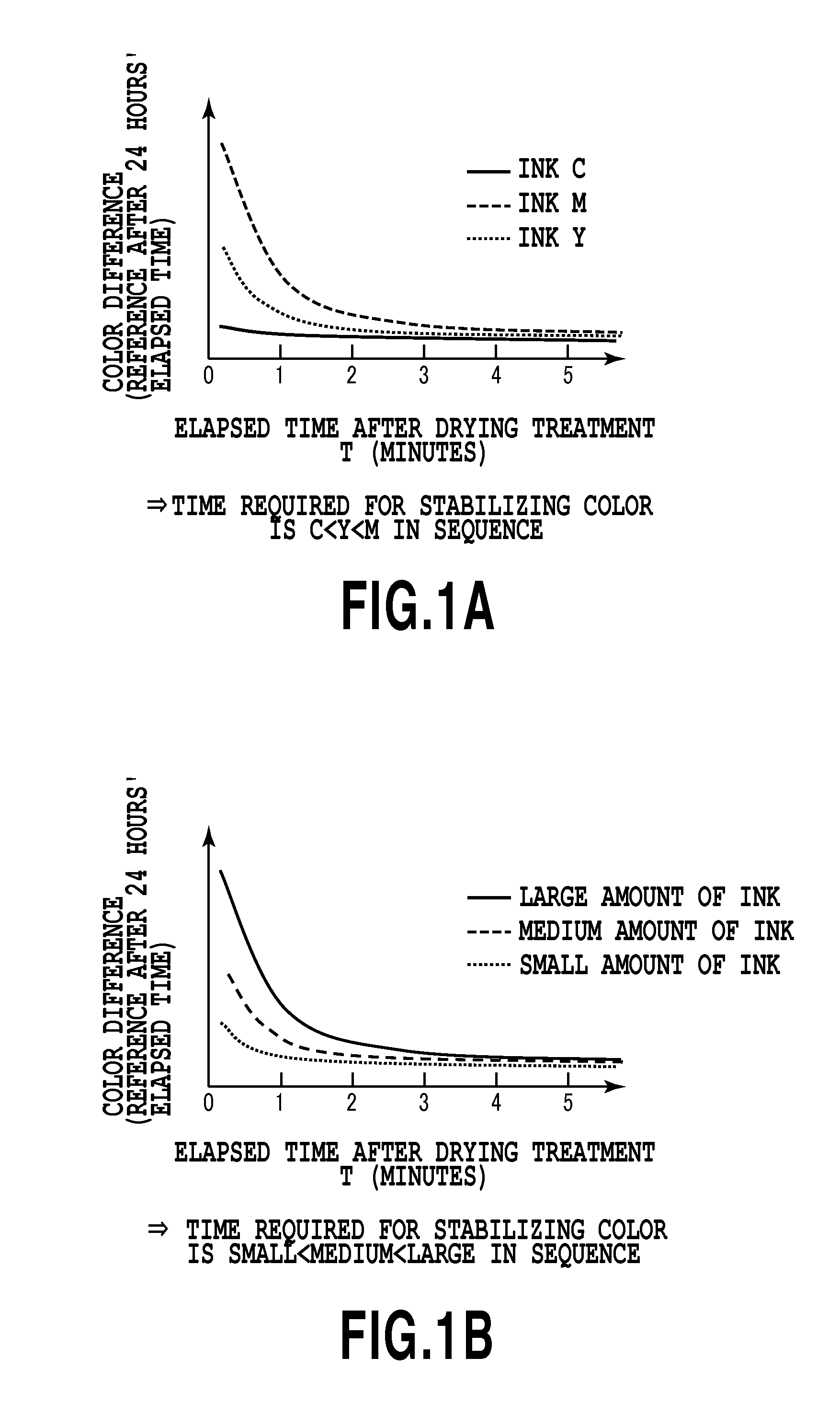
[0049]As described above, a time period required for stabilizing the color after drying varies depending on conditions such as an ink t...

third embodiment

[0051]A third embodiment of the present invention permits selectively performing the mode 1 in which the aforementioned primary color patches are printed and calibration is performed on the basis of them or the mode 2 in which patches are printed with different colors such as secondary colors overlapping those of the primary colors and calibration is performed on the basis of them. According to the present embodiment, these modes for calibration are associated with a type of printing paper on which an image for calibration is printed, that is, a type of the printing paper used for printing, as will be described later. For example, in the case where printing is performed with different colors of inks being overlapped each other, if a printing paper whose color development largely changes is used, calibration is performed in the mode 2.

[0052]FIG. 7A is a view of an image for calibration in the mode 1 for primary colors. FIG. 7B is a view of an image for calibration in the mode 2 for s...


PUM


Abstract

A waiting time Ts is decided on the basis of ink type information and ink feed amount information, referring to waiting time table A (Step 6). Along with this, a dried printing paper is carried to and stopped in a waiting area 9 (Step 7), a time period T is measured after stopping, and measurement processing in the next step is delayed until the time period T reaches the waiting time Ts. Then, when the time period T reaches the waiting time Ts, a measuring instrument 10 is used to measure a density of a patch printed on the printing paper (Steps 8 and 9).

Description

BACKGROUND OF THE INVENTION[0001]1. Field of the Invention[0002]The present invention relates to an inkjet printing apparatus and a calibration method, specifically, an art to measure an image when the color and color density of an image printed with ink is measured and printing properties of the printing apparatus are calibrated on the basis of the measured result.[0003]2. Description of the Related Art[0004]When calibration is performed, a patch for measurement is first printed. A printing paper on which this patch was printed has relatively large difference in its moisture content between immediately after printing and after fixing a color, due to ink ejected onto the printing paper, so that much difference of color between them occurs. Therefore, in calibration, it is preferable that measurement is performed in a final state of the printing paper, that is, a state where the printing paper is dried and the color is stabilized. In doing so, since natural air drying takes much time...

Claims


Application Information

Patent Timeline
Patent Type & Authority Patents(United States)
IPC IPC(8): H04N1/46G06K9/00B41J2/165H04N1/60B41J2/01
CPCH04N1/6033
Inventor MURO, KENTAROUHIROSAWA, SUSUMUKANO, YUTAKANAGOSHI, SHIGEYASUTESHIGAWARA, MINORUMURAYAMA, YOSHIAKIMURASE, TAKESHIAZUMA, SATOSHIKATO, MASAOKATO, MINAKO
Owner CANON KK
Learn More