
Apparatus abnormality diagnosis method and system

a technology for abnormalities and diagnostic methods, applied in the field of abnormality diagnosis and system, can solve the problems of disadvantageous reduction of maintenance operations, many types of apparatus failures, and methods of operation all types of failures have not yet been established in advance, and achieve the effect of efficiently achieving abnormality diagnosis and detection, easy reflection onto the model, and easy creation

Inactive Publication Date: 2014-03-18
HITACHI LTD
View PDF13 Cites 10 Cited by
  • Summary
  • Abstract
  • Description
  • Claims
  • Application Information

AI Technical Summary

Benefits of technology

[0015]However, to create or update a model, a human operation is required. Inputting information of failure cases itself requires many processes, thereby increasing cost. In particular, as the number of apparatuses to be diagnosed and the number of types of failures increase, the number of processes required to input information of failure cases necessary for abnormality diagnosis increases, thereby making operation of actual system difficult.
[0031]The effects obtained by typical aspects of the present invention will be briefly described below. According to a typical embodiment of the present invention, the present invention relates to an apparatus abnormality diagnosis system capable of easily creating, adding, and updating a model (an diagnosis model) for an initial and new (additional / updating) failure case and, by using this model, capable of appropriately and efficiently achieving an abnormality diagnosis and detection, an instruction for operation and maintenance, and others.

Problems solved by technology

On the other hand, in an apparatus as being complicated and multifunctioned, there are many types of apparatus failures.
However, methods of operation all types of failures have not yet been established in advance.
In such maintenance operations depending on the knowledge of the operators, as the number of apparatuses to be handled increases, the quality of maintenance operations may disadvantageously decrease.

Method used


Image

  • Apparatus abnormality diagnosis method and system
  • Apparatus abnormality diagnosis method and system
  • Apparatus abnormality diagnosis method and system

Examples


Embodiment Construction

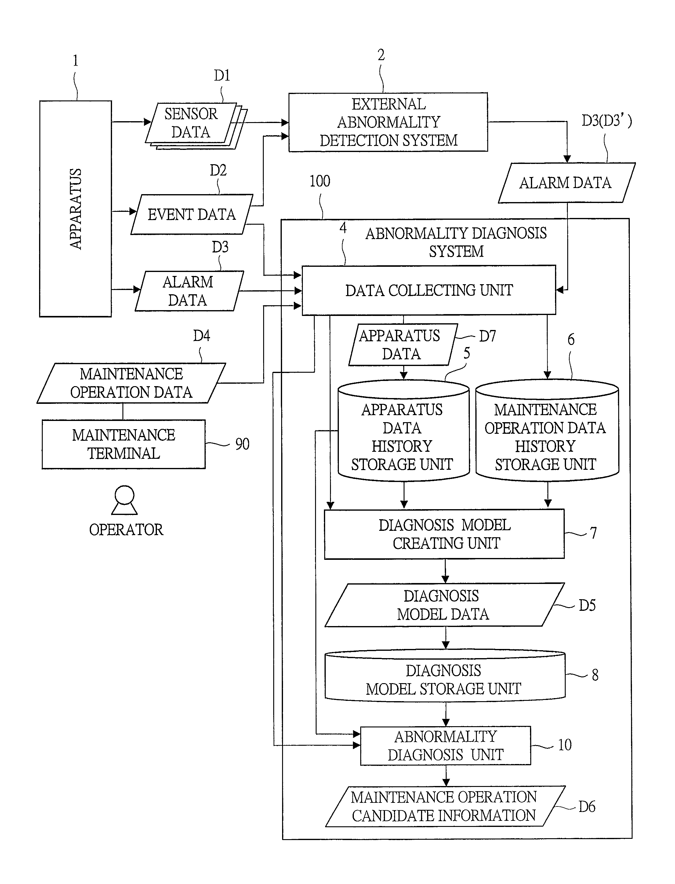
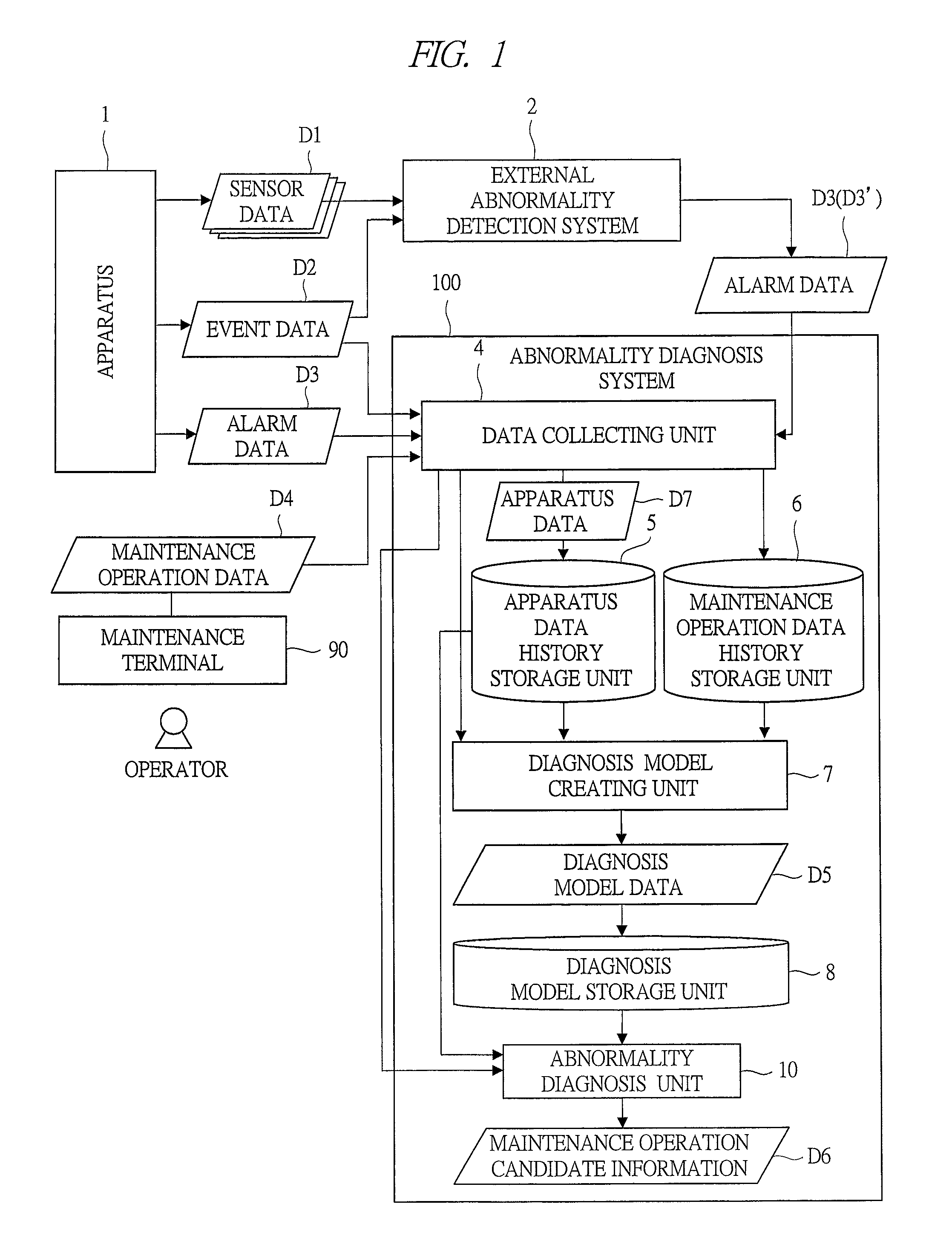
[0054]Hereinafter, embodiments of the present invention (apparatus abnormality diagnosis method including an apparatus diagnosis model creating method, and an information processing system carrying out a processing according to the method) will be described in detail with reference to the accompanying drawings (FIGS. 1 to 21). Note that components having the same function are denoted by the same reference symbols throughout the drawings for describing the embodiment, and the repetitive description thereof will be omitted. The present diagnosis method is a method of using an diagnosis model created by the present creating method and, when a sign of abnormality of a target apparatus is detected or an abnormality occurs, diagnosing its cause.

[0055]In the system of the present embodiment, in summary, in a structure as depicted in FIG. 1, in a process of creating an diagnosis model targeted for an apparatus 1 (FIG. 5), a structured abnormality model having a graph network structure among...


PUM


Abstract

A technique relating to an apparatus abnormality diagnosis system, capable of easily creating and adding / updating an diagnosis model with respect to an initial and new failure case, and appropriately and efficiently achieving diagnosis of abnormality and instruction of operation using the model. In the abnormality diagnosis system, an diagnosis model creating process unit creates a structured abnormality model expressing a structured abnormality of maintenance operation type to an alarm and apparatus event relating to the maintenance operation type by a graph network structure based on acquisition of maintenance operation data. And, by synthesizing the structured abnormality model with an existing structured abnormality model, the diagnosis model is updated.

Description

TECHNICAL FIELD[0001]The present invention relates to technologies for analysis, detection, maintenance, and others of apparatuses (such as equipment) and, in particular, to a method and system of creating an diagnosis model for diagnosing a cause when a sign of abnormality of an apparatus is detected or an abnormality occurs and making an instruction about operation, maintenance details, or others.BACKGROUND ART[0002]In various apparatuses, such as cogeneration apparatuses and vacuum apparatuses, for example, a stable operation without a failure is a minimum function required. Also, even when the apparatus becomes out of order, the apparatus has to be recovered to a normal state as soon as possible. On the other hand, in an apparatus as being complicated and multifunctioned, there are many types of apparatus failures. However, methods of operation all types of failures have not yet been established in advance. Therefore, when a sign of abnormality is detected or an abnormality occu...

Claims


Application Information

Patent Timeline
Patent Type & Authority Patents(United States)
IPC IPC(8): G05B23/02G06F7/60G06F11/34G06Q50/10G06F11/22G06F11/30G06F11/00G06Q50/00G06G7/48
CPCG05B23/0283G06F11/3476G05B23/0278
Inventor MIWA, TOSHIHARUTAMAKI, KENJI
Owner HITACHI LTD
Learn More