Precision water jet disruptor delivery system

a technology of water jets and disruptors, applied in the direction of explosive charges, white arms/cold weapons, weapons, etc., to achieve the effects of low cost, low shrapnel production, and low cos

Active Publication Date: 2014-03-25
ROCK THOMAS MICHAEL +1
View PDF21 Cites 16 Cited by
  • Summary
  • Abstract
  • Description
  • Claims
  • Application Information

AI Technical Summary

Benefits of technology

[0095]In many dangerous and under certain situations a robot may be used to deliver and position the disruptor. Ideally the robot may be used repetitively and with only the probe arm being destroyed. However, often the explosions of disruptors tend to damage and destroy robots. The invention couples a low cost robot with the explosively driven water jet disruptor to create a compact, lightweight, and low shrapnel producing system. The low cost robots have small amounts of metal parts, batteries, and plastic exteriors, which lead to a low production of shrapnel.
[0096]The invention provides an all plastic system that minimizes the creation of dense metal shrapnel. We can incorporate metals in the supersonic jet, but only just sufficient to provide the particular jet properties. Metal components such as the robot and laser alignment system may incorporate metal objects, but these can be minimized.
[0097]The invention creates a cutting die in the lid of the assembly that allows the user to press-cut the plastic explosive and fill the cutting die. The plastic explosives within the die are pressed up against the blasting cap holder where the blasting cap will make detonation initiation. The plastic explosive does not extrude thro

Problems solved by technology

Alford describes collimation of projectiles a

Method used


Image

  • Precision water jet disruptor delivery system
  • Precision water jet disruptor delivery system
  • Precision water jet disruptor delivery system

Examples


Embodiment Construction

[0211]Several typical embodiments of the invention are illustrated in the following frames. In these drawings several variations in assembly and arrangements will be shown.

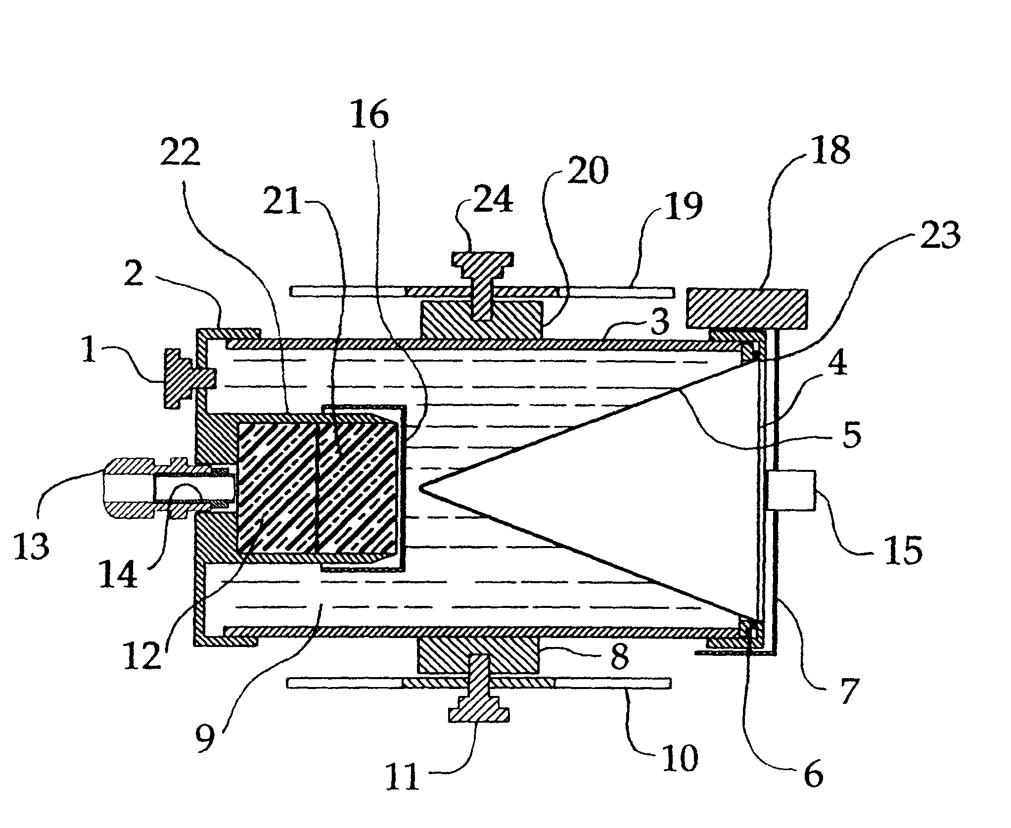
[0212]In FIG. 1 a cross-sectional view of the disruptor assembly is shown. All the components shown in this diagram are typically made out of plastics, rubber, and water, except for the lasers 15, 18, to minimize the potential for spark generation and initiation of detonations. The disruptor consists of the components of a clear acrylic plastic, polycarbonate, polystyrene, or polyethylene terephthalate outer cylinder 3, polyethylene plastic end cap 4 with a vent hole and knurled nylon screw 1 ABS in plastic holding cap 2. On end of the cap 2 and on the centerline of the end cap 2 the assembly of the blasting cap clamp 13 and positioning sleeve 14 are screwed into the polyethylene end cap 2. Two cylinders of plastic explosive disks 12, 21 are shown contained by the cutting die 22 of the end cap 4. The plastic explo...


PUM


Abstract

A precision coaxial water jet disruption explosive device system that holds a blasting cap precisely to the surface of a cylindrically cut positioned plastic explosive that couples a detonation shock wave into water surrounding a hollow forming cavity. A pressure relief vent enables the water filled system to be assembled without deforming the thin walled hollow jet forming cavity, enabling forming repeatable supersonic jets on centerline axis. This system is positioned with two triangular pivot legs and aligned with two fan light beams or a line sight to define a projected jet route to deliver a water jet that can cut through over 1 inch of steel and disrupt target objects more than 9 feet away. This system is used to disable improvised explosive devices, and other dangerous objects, without detonating the targeted explosives and electronic devices such that the contents are destroyed without explosion sequences occurring.

Description

[0001]This application claims the benefit of U.S. Provisional Application No. 61 / 469,155, filed Mar. 30, 2011, which is hereby incorporated by reference in its entirety as if fully set forth herein.BACKGROUND OF THE INVENTION[0002]Explosively formed water jet disruptors use high explosives, typically a shaped plastic explosive, to create a shock wave traveling through water or some other liquefying medium to collapse onto a forming cavity. This shock wave collapse by its geometry and the dynamic transit of the shock wave along the forming can create a supersonic jet of water that is ejected from the system. These supersonic water jets can be used to penetrate through walls such as mild steel plate that is over an inch thick. A very useful application, because the water jet it's non-sparking generating penetration, is to disrupt improvised explosive devices by severing the explosive sequence system and dispersing the improvised device explosives without detonating their explosives Pr...

Claims


Application Information

Patent Timeline
IPC IPC(8): F42B1/02
CPCF42B1/02F42B1/028F41G1/35F41B9/0046
Inventor ROCK, THOMAS MICHAELSMITH, LANEY ALAN
Owner ROCK THOMAS MICHAEL
Why Eureka
Try Eureka