Endo-tracheal intubation device with adjustably bendable stylet

a technology of trachea intubation and bendable stylet, which is applied in the field of medical devices, can solve the problems of spinal cord injury, special challenge to medical practitioners, and patients with more difficult airway access

Active Publication Date: 2014-03-25
SYNCRO MEDICAL INNOVATIONS
View PDF21 Cites 26 Cited by
  • Summary
  • Abstract
  • Description
  • Claims
  • Application Information

AI Technical Summary

Benefits of technology

[0009]The object of this invention is to provide a disposable, inexpensive-to-manufacture endo-tracheal tube placement device which includes components useful for visualizing key anatomical structures which a medical practitioner encounters in the course of gently pushing a portion of a tube placement device between a patient's vocal cords and into his trachea, the portion so pushed being encased in the endo-tracheal tube prior to its insertion into the patient's airway, said portion being adjustably bendable in such a way that the endo-tracheal tube can be inserted into the patient's trachea even when visualization of the anatomical structures is difficult because of the shape of the patient's throat and / or because of injury.
[0010]A further object is to provide an endo-tracheal intubation device which paramedical personnel, after a brief training exercise in its applications, can safely use to assist a patient experiencing a compromised airway.
[0013]Distal from the stylet holder, the end of the tubular element is covered by a metal cap which preferably also encases a disk to which the flexible wire is affixed and on which a LED light is mounted in such a way that it protrudes outwardly from the stylet's tip. Bright enough to be seen through the skin of a patient's neck in a darkened setting, the LED light allows the user to track the endo-tracheal tube's advancement along the patient's airway, as well as to visualize his vocal cords. In the preferred embodiment, the LED light is powered by at least one battery housed within the stylet holder and is activated by a sliding, on-and-off switch mounted thereon.
[0014]Proximate with the metal cap, the stylet's tubular element is scored in such a way that it can be bent in a controlled manner by tensioning the flexible wire, without disturbing electrical wires, connecting the LED light to the battery, which also run through the tubular element. In the preferred embodiment, the scored portion of the tubular element defines a series of spaced apart, transverse slots so positioned that the mid-section of each slot is disposed on only one side of the unbent stylet's longitudinal centerline, away from the electrical wires, thereby minimizing their exposure to the slots, each of which is squeezed so as to narrow its width, closing it to a degree, whenever the stylet is flexed.
[0015]Means for tensioning the flexible wire includes the bell crank which is pivotally mounted on a forked structure situated at the stylet holder's terminal end distal from the cylindrically-shaped void. The forked structure, which defines a U-shaped channel with opposing side walls, generally straddles the bell crank's short arm to which the flexible wire is affixed. By rotating the bell crank's trigger arm toward the stylet holder and, in the process, simultaneously moving the short arm away from the through passageway and its opening into the U-shaped channel—an opening which is located approximately midway between the opposing side walls, one can pull a short portion of the flexible wire outwardly from the through passageway, thereby reducing, while the trigger arm is so rotated, the length of the flexible wire retained within the tubular element and flexing the stylet. Moreover, the further the trigger arm is rotated in a direction toward the stylet holder so as to bring the trigger arm's longitudinal centerline more nearly into generally parallel alignment with the path which the flexible wire takes, under tension, between the through passageway's respective junctures with the cylindrically-shaped void and the U-shaped channel, the greater is the flexing of the stylet.

Problems solved by technology

Some patients present more difficult airway access than others.
This presents a special challenge to the medical practitioner.
In such situations, if one were to extend the neck in the usual fashion, that is, in such a way that one can visualize the vocal cords by using a direct laryngoscope in order to insert the endo-tracheal tube, one could injure the spinal cord, causing severe paralysis or even death.
Prolonged intubation procedure time can result in various degrees of brain injury.
Such placement can result in patient hypoxia, varied degrees of brain damage and / or death.
However, in other patients, the vocal cords are completely hidden from view, making insertion of the intubation device difficult.
Often it is helpful to extend the patient's head backward as far as possible to increase the medical practitioner's view of the vocal cords; but such an approach cannot be used if the patient has suffered a neck injury and has to be made immobile in order to prevent further damage.
In practice then, physical and anatomical variations among patients can make it difficult for a medical practitioner to clearly identify a particular individual's vocal cords.
Unless they can be properly identified, however, they may be damaged during ah intubation procedure.
Unfortunately, this prior art combination is too costly to be disposed of after a single patient use; and the probability of infectious materials being transmitted from one patient to another is high—especially during a medical emergency in which more than one airway-compromised patient is involved and the same imaging device must be reused immediately.

Method used


Image

  • Endo-tracheal intubation device with adjustably bendable stylet
  • Endo-tracheal intubation device with adjustably bendable stylet
  • Endo-tracheal intubation device with adjustably bendable stylet

Examples


Embodiment Construction

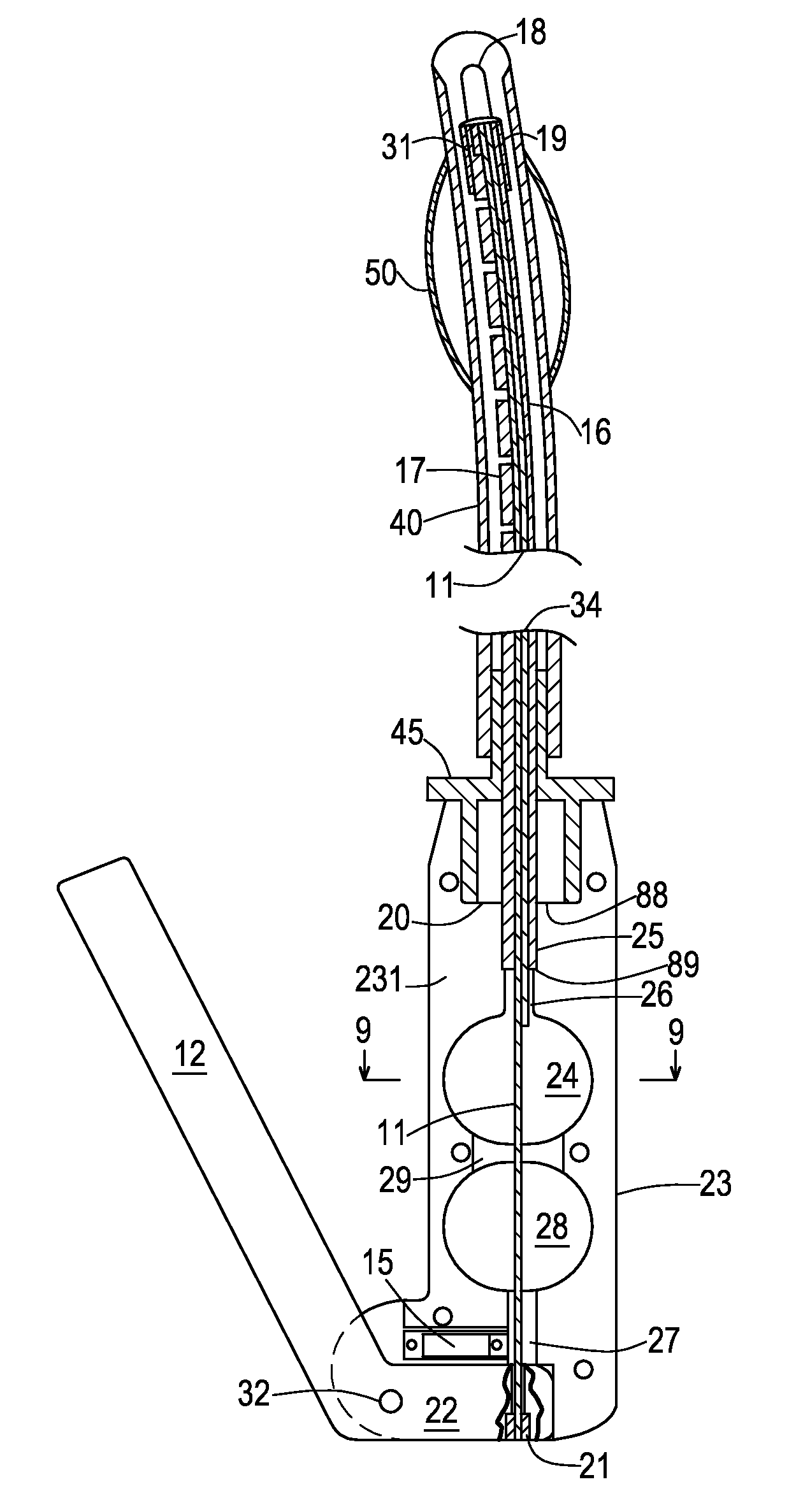
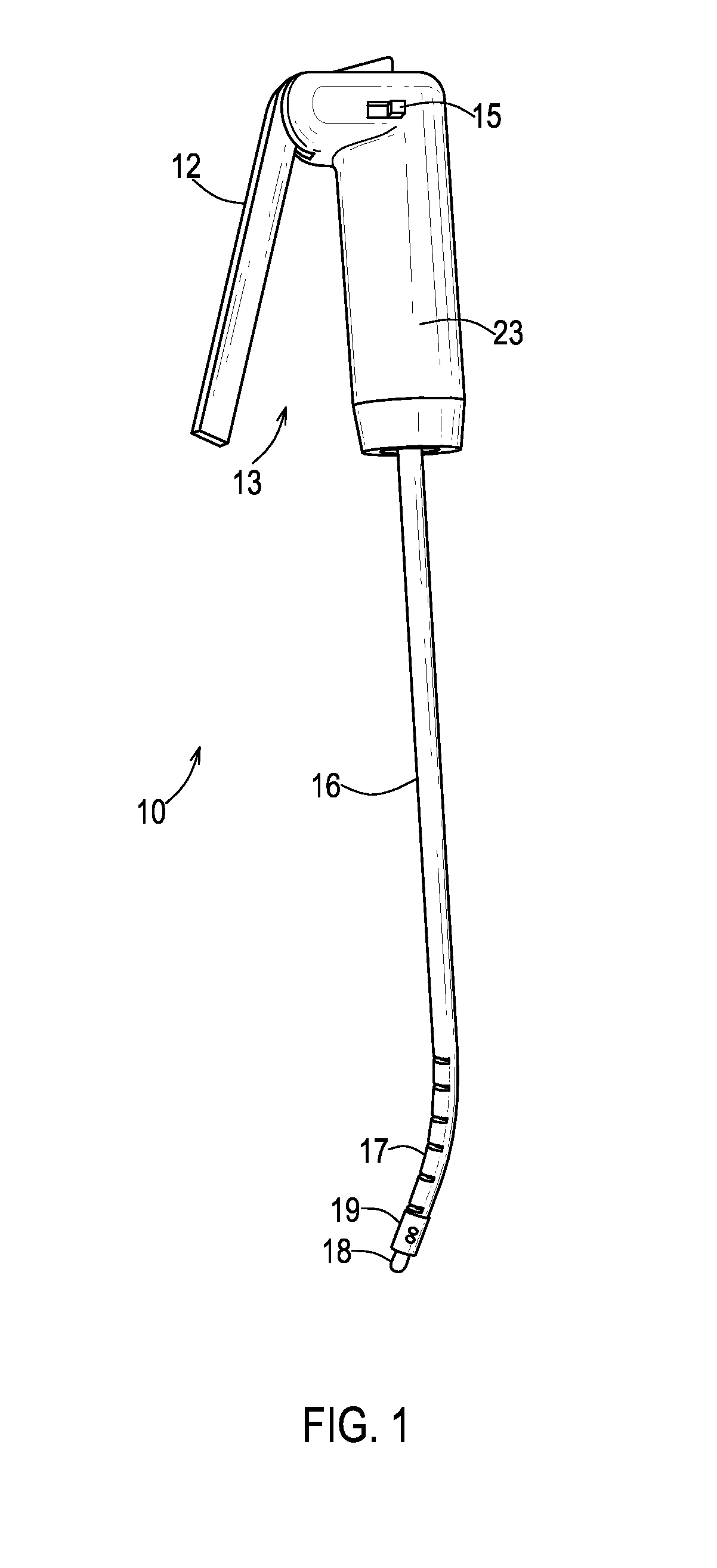
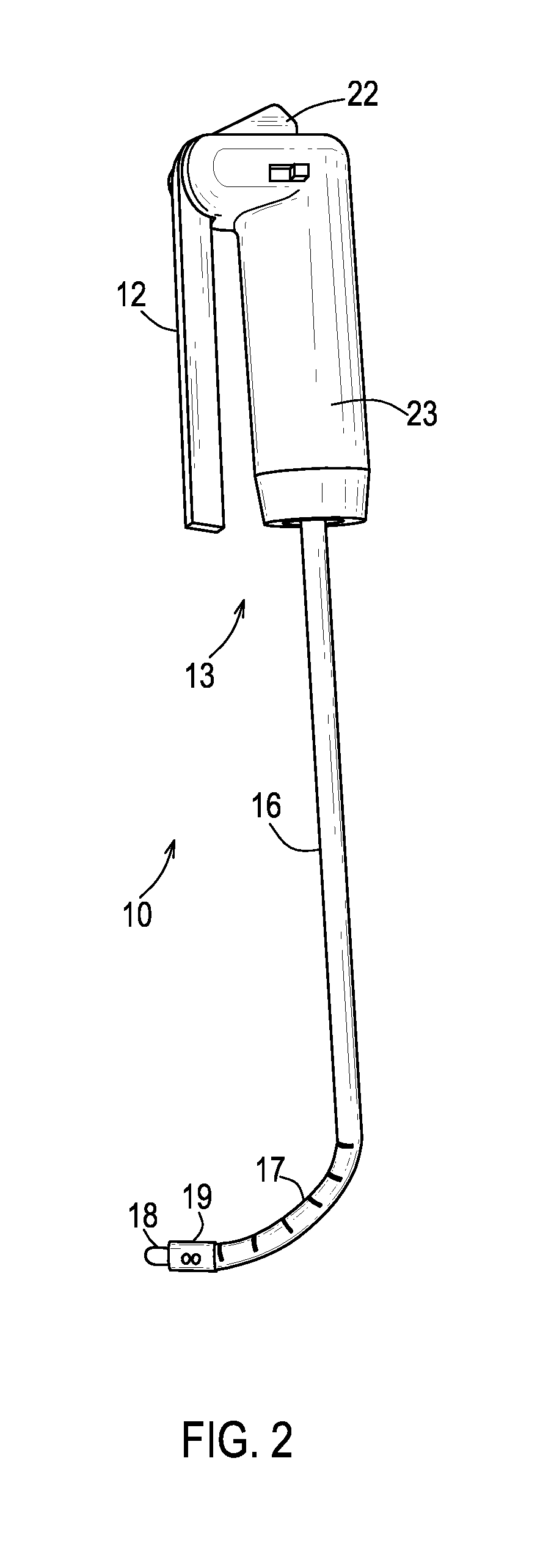
[0030]In the drawings, an improved endo-tracheal intubation device is indicated generally by the reference numeral 10. The device 10, designed for single use only, provides its own bright, battery-powered LED light 18 to illuminate the vocal cords of a patient's larynx so that a medical practitioner can visualize them directly in certain individuals—specifically, those whose neck can be hyper-extended in such a fashion that anatomical structures along the patient's airway are aligned linearly—and, more generally, to enable a trained observer to confirm placement of a conventional endo-tracheal tube 40 in the trachea, as can be determined by observing the position of the device's light as it shines through the skin of the patient's neck. Coupled with this low cost visualization tool is a novel mechanism which allows the operator to deflect the tip of the endotracheal tube 40 towards the vocal cords, thereby facilitating its proper placement anteriorly in the trachea.

[0031]Basic to th...


PUM


Abstract

An inexpensive, endo-tracheal intubation device is disclosed. Methods of making and using the inexpensive, endo-tracheal intubation device are also disclosed.

Description

CROSS-REFERENCE TO RELATED APPLICATION[0001]This application is a non-provisional application of the earlier filed provisional application, Ser. No. 61 / 343,413, filed on Apr. 28, 2010, and claims the benefit of priority of the filing date of Apr. 28, 2010, pursuant to 35 U.S.C. Sec. 119(e).FIELD OF THE INVENTION[0002]The present invention relates generally to medical devices designed to improve airway tube placement and, more specifically, to such devices which allow a medical practitioner to insert an airway tube rapidly and properly in a patient's trachea.BACKGROUND OF THE INVENTION[0003]In a medical emergency, it is frequently necessary for the medical practitioner to insert a breathing tube into the patient's trachea so that he or she can be ventilated. The tube must enter the larynx and pass through the opening between the vocal cords. Care must be taken during insertion to prevent the tube from entering the esophagus.[0004]Some patients present more difficult airway access tha...

Claims


Application Information

Patent Timeline
Patent Type & Authority Patents(United States)
IPC IPC(8): A61M16/00
CPCA61B1/2673A61B1/0684A61M16/0488
Inventor GABRIEL, SABRY
Owner SYNCRO MEDICAL INNOVATIONS
Why Eureka
Try Eureka