Work vehicle-mounted engine device

Active Publication Date: 2014-03-25
YANMAR POWER TECHNOLOGY CO LTD
View PDF16 Cites 1 Cited by
  • Summary
  • Abstract
  • Description
  • Claims
  • Application Information

AI Technical Summary

Benefits of technology

[0021]According to the invention, an air cleaner is arranged on the side of the exhaust gas cleaning device at a position lower than an upper end of the engine, so that the exhaust gas cleaning device and the air cleaner can be compactly arranged between the inner surface of the hood and the engine. The height of the upper surface of the hood with respect to the earth can be decreased as compared with a structure in which the exhaust gas cleaning device and the air cleaner are arranged on the upper surface side of the engine. Moreover, the upper surface side of the engine is arranged close to the hood and the exhaust gas cleaning device is arranged close to the air cleaner, so that the temperature of the exhaust gas cleaning device (exhaust gas in the exhaust gas cleaning device) can be kept by the exhaust heat from the engine and the exhaust gas cleaning device, and the air cleaner can be easily heated.
[0022]According to the invention, a counter weight is fitted on a side portion of a machine body and a through hole is formed in the counter weight and an exhaust outlet side of an exhaust gas pipe is faced to the through hole, so that an exhaust gas outlet side of the exhaust gas cleaning device can be made to communicate with the through hole at an extremely close range. This makes it possible to form the exhaust gas pipe in a short length and to improve the workability of a fitting work.
[0023]According to the invention, a counter weight is fitted on a side portion of the machine body and a through hole is formed in the counterweight and the exhaust outlet side of the exhaust gas pipe is passed through the through hole, so that the exhaust gas pipe can be extended on the outsi

Problems solved by technology

However, especially in a work vehicle such as a backhoe, a turning radius is required to be made as small as possible in order to prevent the work vehicle from coming into contact with its surroundings, so that a machine body itself needs to be made compact in size and is limited (narrow) in the mounting space in many cases.
Moreover, in addition to the problem that the mounting space is limited in size, ther

Method used


Image

  • Work vehicle-mounted engine device
  • Work vehicle-mounted engine device
  • Work vehicle-mounted engine device

Examples


Embodiment Construction

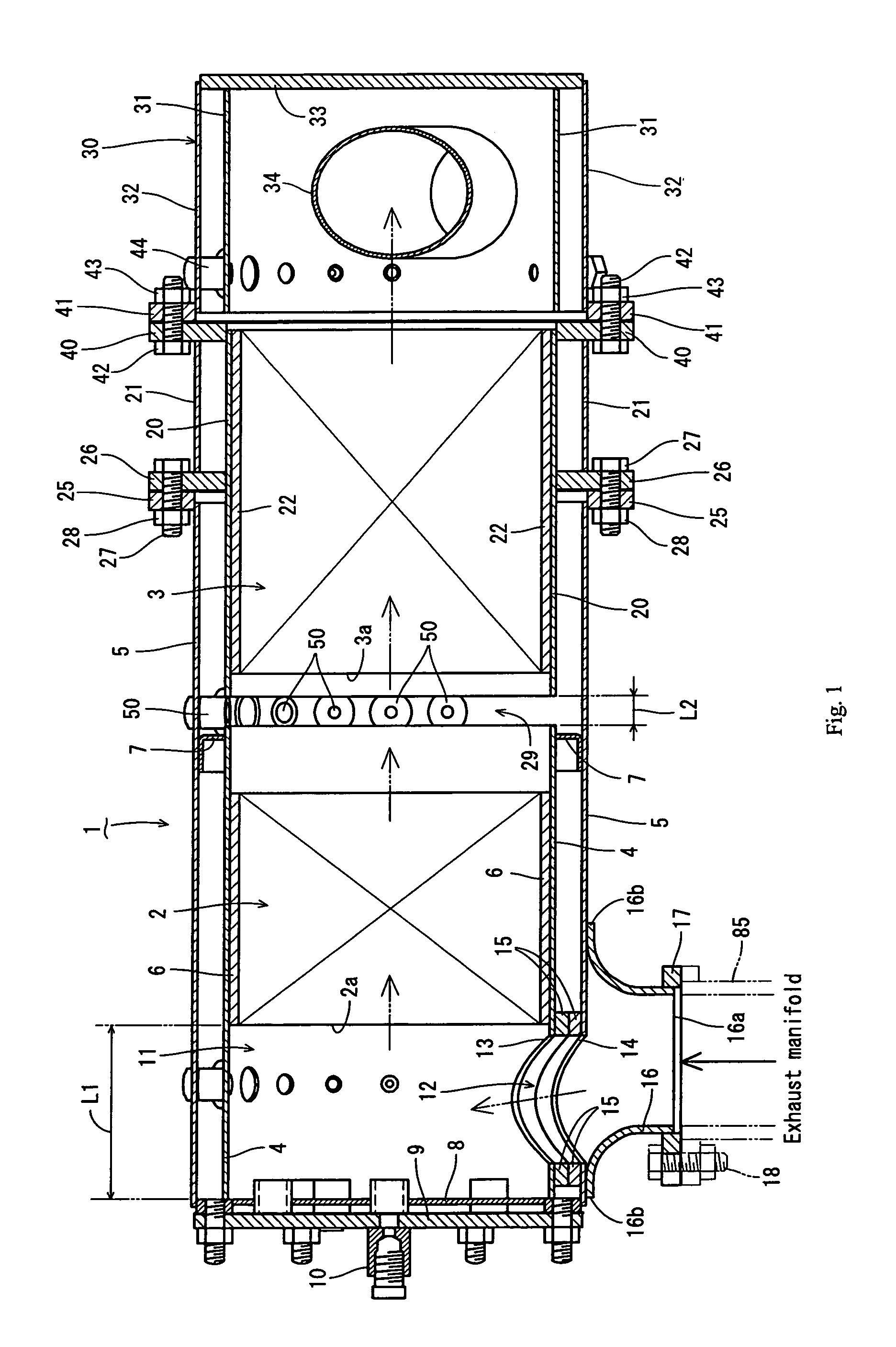
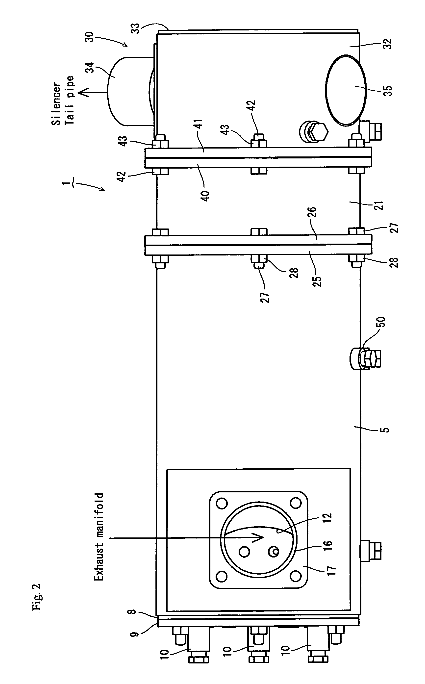
[0051]Hereinafter, an embodiment to embody the present invention will be described on the basis of the drawings. Here, in the following description, an exhaust gas inflow side is simply referred to as a left side and an exhaust gas outflow side is simply referred to as a right side.

[0052]First, the general structure of an exhaust gas cleaning device will be described with reference to FIG. 1 to FIG. 9. As shown in FIG. 1 to FIG. 5, the exhausted gas cleaning device of the present invention is provided with a continuous regeneration type diesel particulate filter 1 (hereinafter referred to as “DPF”). The DPF 1 is used to physically collect particulate matter (PM) or the like in exhaust gas. The DPF 1 has a structure in which a diesel oxidation catalyst 2 such as platinum for producing nitrogen dioxide (NO2) and a honeycomb structured soot filter 3 for continuously oxidizing and removing the collected particulate matter (PM) at a comparatively low temperature are arranged in series in...


PUM


Abstract

A work vehicle limited in a mounting space is adapted to have an engine, which is provided with an exhaust gas cleaning device, easily arranged therein. An engine device, which is to be mounted on the work vehicle, is provided with the engine mounted on a machine body and covered with a hood, an air cleaner for cleaning air introduced into the engine, and an exhaust gas cleaning device for cleaning exhaust gas from the engine. The exhaust gas cleaning device is arranged on a flywheel housing fitted on one side portion of the engine.

Description

TECHNICAL FIELD[0001]The present invention relates to an engine device used for a work vehicle such as a backhoe, a crane car, a fork lift, and a tractor and, more particularly, to an engine and an engine device of an exhaust gas cleaning device and the like which are arranged in a work vehicle.BACKGROUND OF THE INVENTION[0002]There has been known a technology in which a diesel particulate filter (or NOx catalyst) or the like is arranged as an exhaust gas cleaning device (after-treatment device) in an exhaust gas path of a diesel engine and in which exhaust gas exhausted from the diesel engine is cleaned by the diesel particulate filter (or NOx catalyst) or the like (see patent literature 1, patent literature 2, and patent literature 3). Further, there has been also known a technology in which a filter case (inner case) is fitted in a casing (outer case) and in which a particulate filter is arranged in the filter case (see patent literature 4).CITATION LIST[0003]Patent document 1: J...

Claims


Application Information

Patent Timeline
IPC IPC(8): B60K13/04
CPCF02M35/04B60K13/04F01N13/08F02M35/164F02B3/06F01N2590/08F02B67/00F02M35/16
Inventor MITSUDA, MASATAKAONODERA, TAKAYUKI
Owner YANMAR POWER TECHNOLOGY CO LTD
Why Eureka
Try Eureka