
Plasma-shell PDP

a shell and plasma shell technology, applied in the direction of gas-filled discharge tubes, electric discharge tubes, coatings, etc., can solve the problems of difficult control of the amount and composition of gas remaining in the shell, the shell shells are not uniform, and the gaseous xenon, argon and krypton used in plasma displays may be too large to be permeated through the frit material or the wall of the microsphere, etc., to achieve the effect of increasing the strength of the shell

Inactive Publication Date: 2014-04-01
IMAGING SYST TECH
View PDF3 Cites 4 Cited by
  • Summary
  • Abstract
  • Description
  • Claims
  • Application Information

AI Technical Summary

Benefits of technology

The processes described in this patent can produce small hollow plasma-shells, such as spheres, discs, and domes, filled with ionizable gas for use in display devices. These shells have a uniform thickness and can be filled with a specific gas composition and pressure. The plasma-shell can also contain luminescent materials or other secondary electron emission materials to enhance the gas discharge of the plasma display panel. The strength of the shell can be increased by conducting the removal process under oxidizing conditions such as in an oxygen-rich environment, which helps remove any residual carboneous material.

Problems solved by technology

Some gases such as xenon, argon, and krypton used in plasma displays may be too large to be permeated through the frit material or wall of the microsphere.
Because the shells cool and drop at the same time, the shell shells do not form uniformly.
It is also difficult to control the amount and composition of gas that remains in the shell.
However, shell uniformity may be difficult to control.

Method used


Image

  • Plasma-shell PDP
  • Plasma-shell PDP
  • Plasma-shell PDP

Examples


Embodiment Construction

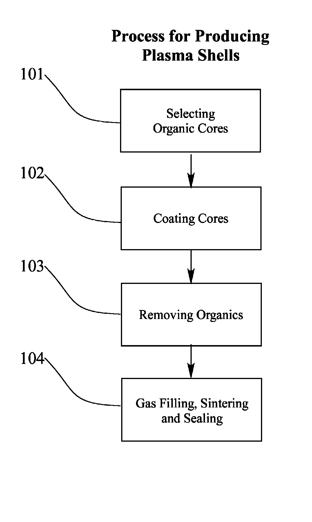
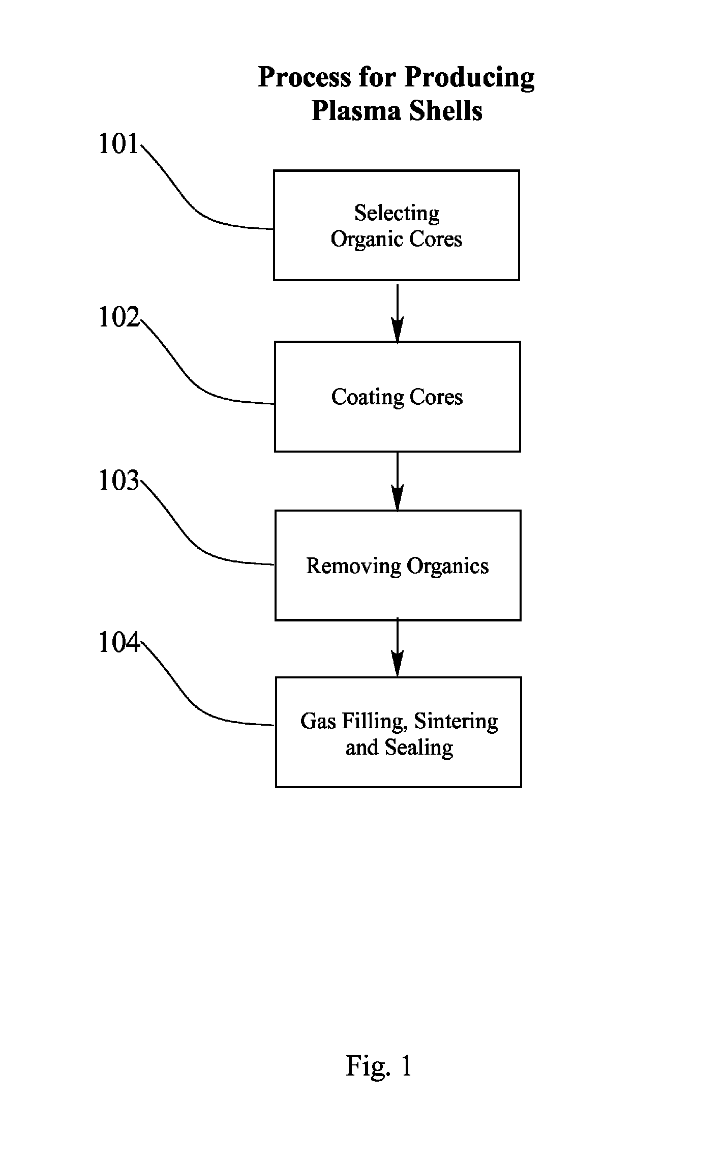
[0105]FIG. 1 shows the process steps to produce shells possessing the desired characteristics for use as the light-emitting element of a gas discharge plasma display device (PDP).

[0106]In Step 101, solid organic cores of predetermined geometric shape and size are selected by sieve or other means to produce the desired inner diameter and geometric shape of the shell. To produce Plasma-domes, the cores may be dome shaped. Typically the cores are selected with a diameter of 25 to 50 percent greater than the desired Plasma-shell diameter as the slurry of particles will tend to shrink as it is fired. The organic core may be selected based on geometric shape and density. Low density polystyrene beads of a predetermined shape are suitable for this process. Although sieving may be used as the first process step, the sieving may be repeated later in the process, for example after the formation of the bisque shells.

[0107]In Step 102, the organic core particles are coated with an aqueous and / o...


PUM


Abstract

A process for the manufacture of a hollow gas-filled Plasma-shells for a gas discharge device. The Plasma-shell is located in or on a substrate within the device with a dome side or flat side facing the viewing direction.

Description

RELATED APPLICATIONS[0001]This application is a continuation-in-part and division under 35 U.S.C. 120 of copending U.S. patent application Ser. No. 12 / 108,716 filed Apr. 24, 2008 which claims priority under 35 U.S.C. 120 as a divisional application which claims priority from U.S. application Ser. No. 10 / 986,325, now abandoned, filed Nov. 12, 2004, which claims priority under 35 U.S.C. 119(e) for Provisional Application Ser. No. 60 / 519,262, filed Nov. 13, 2003.FIELD OF THE INVENTION[0002]This invention relates to the production of small hollow shells such as Plasma-domes filled with an ionizable gas at a predetermined pressure and the use of gas filled shells in a gas discharge plasma display panel (PDP) device to create an enclosed pixel or cell structure. The construction of a PDP out of gas filled shells is known in the prior art. Such shells are referred to in the art as microspheres, spheres, beads, ampoules, capsules, bubbles, and so forth. In the practice of this invention, a ...

Claims


Application Information

Patent Timeline
Patent Type & Authority Patents(United States)
IPC IPC(8): B05D5/06
CPCH01J11/18H01J11/00B05D5/06C09K11/00
Inventor WEDDING, CAROL ANNSTRBIK, III, OLIVER M.WEDDING, DANIEL K.GUY, JEFFREY W.WENZLAFF, ROBERT P.
Owner IMAGING SYST TECH
Learn More