Positive and negative obstacle avoidance system and method for a mobile robot

a technology of positive and negative obstacles and avoidance systems, applied in the field of mobile robots, can solve the problems of not working well for detecting positive, mobile robots that use horizontally oriented lasers for detecting obstacles also have problems detecting and avoiding unexpected, etc., to improve the ability of mobile robots to detect and reduce the number of false positives

Active Publication Date: 2014-04-01
ORMON CORP
View PDF48 Cites 31 Cited by
  • Summary
  • Abstract
  • Description
  • Claims
  • Application Information

AI Technical Summary

Benefits of technology

[0013]In another aspect, embodiments of the present invention also provide a negative obstacle avoidance system for use with a mobile robot in a physical environment. The negative obstacle avoidance system operates to prevent the mobile robot from driving into a hole or ditch, driving off the edge of a cliff, or driving across an unacceptably large gap in the floor. In essence, the negative obstacle avoidance system does this by comparing currently-received floor distance readings from one or more non-horizontally-oriented lasers with a tolerance profile, which defines, among other things, the largest gap in the floor (i.e., a “gap profile”) that the mobile robot will be permitted to traverse. Embodiments of the present invention, however, also use the tolerance profile settings to avoid recognizing too many false positives in the data, which could arise, for example, when the mobile robot is approaching a relatively safe grating, small bump or small gap in the floor. The tolerance profile settings also reduce the number of false positives that arise when the laser data readings are less than perfect. This might occur, for example, when the laser light coming from the mobile robot strikes something too reflective and at an angle that prevents the light from returning to the sensor, or when the laser light coming from the mobile robot strikes something that is not reflective enough, and therefore absorbs too much of the light for any of it to return to the mobile robot.
[0015]The laser controller receives a set of laser readings from said first laser, each laser reading corresponding to a location in the physical environment within said first plane, and each laser reading comprising a first plane angle and a first plane distance from a given site on the mobile robot. The negative obstacle avoidance engine first converts each laser reading into a three-dimensional coordinate based on the first plane angle, the first plane distance, the first laser position and the first laser tilt. Next, the negative obstacle avoidance engine determines a maximum allowable floor height and a minimum allowable floor height for the three-dimensional coordinate based on the x-component, the y-component and the tolerance profile. The engine then determines if the z-component falls between the maximum allowable floor height and the minimum allowable floor height. If it does, the negative obstacle avoidance system changes an indicator, such as a flag in the memory to designate the x-component and the y-component of the three-dimensional coordinate as the coordinate corresponding to the last good floor reading. If the z-component does not fall between the maximum allowable floor height and the minimum allowable floor height, then the negative obstacle avoidance engine determines whether the distance G between the last good floor reading coordinate and the location in the two-dimensional coordinate system defined by the x-component and the y-component exceeds the maximum allowable floor gap stored in the memory. If the distance G exceeds the maximum allowable floor gap, the negative obstacle avoidance engine adds the x-component, the y-component and the last good floor reading coordinates to the first data structure of two-dimensional coordinates to represent another location in the physical environment to be avoided by the mobile robot. The propulsion system then drives the mobile robot in the physical environment under control of the first data structure, so as to prevent the mobile robot from passing into the locations in the physical environment represented by the two-dimensional coordinates in the first data structure. Thus, the mobile robot, operating under the control of the propulsion system, which itself operates under the influence of the first data structure of two-dimensional coordinates identifying all of the two-dimensional coordinates in the floor plan to be avoided, avoids driving into the gap, ditch or hole, or off of a cliff.

Problems solved by technology

However, they do not work well for detecting positive physical obstacles in the mobile robot's path that are parallel to the floor and / or obstacles that are not at the same height as the horizontally-oriented scanning plane.
This means the mobile robots frequently have no way of detecting and avoiding positive obstacles, such as long tables with legs at the ends (and no legs in the middle), objects suspended from a ceiling or other structure, and obstacles that stick out from the edge of another object, like a keyboard tray.
Mobile robots that use horizontally-oriented lasers for detecting obstacles also have problems detecting and avoiding unexpected negative obstacles, such as a hole in the floor, a descending flight of stairs, the end of a loading dock or the edge of a cliff.
However, there have been a number of significant disadvantages associated with such solutions, including prohibitively-high cost associated with installing, using and maintaining a multiplicity of expensive lasers, and an unacceptably high number of false positives arising, for example, from gratings in the floor, which do not necessarily need to be avoided by the mobile robot.

Method used


Image

  • Positive and negative obstacle avoidance system and method for a mobile robot
  • Positive and negative obstacle avoidance system and method for a mobile robot
  • Positive and negative obstacle avoidance system and method for a mobile robot

Examples


Embodiment Construction

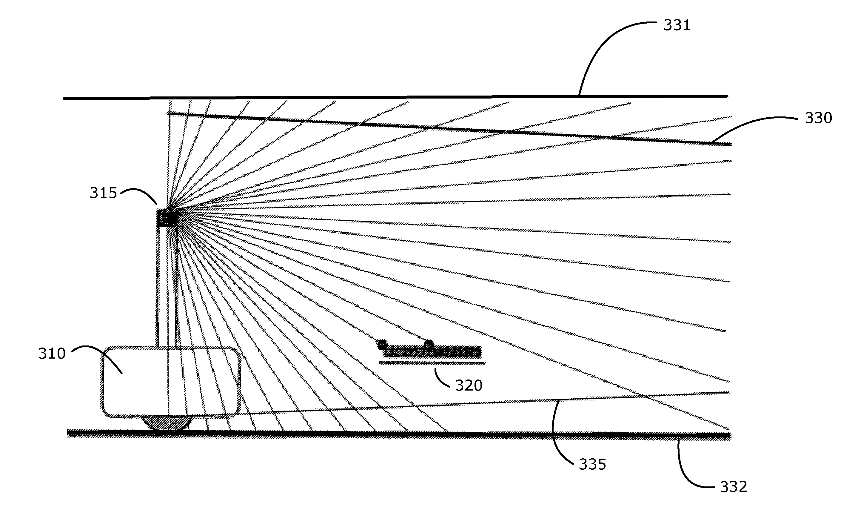
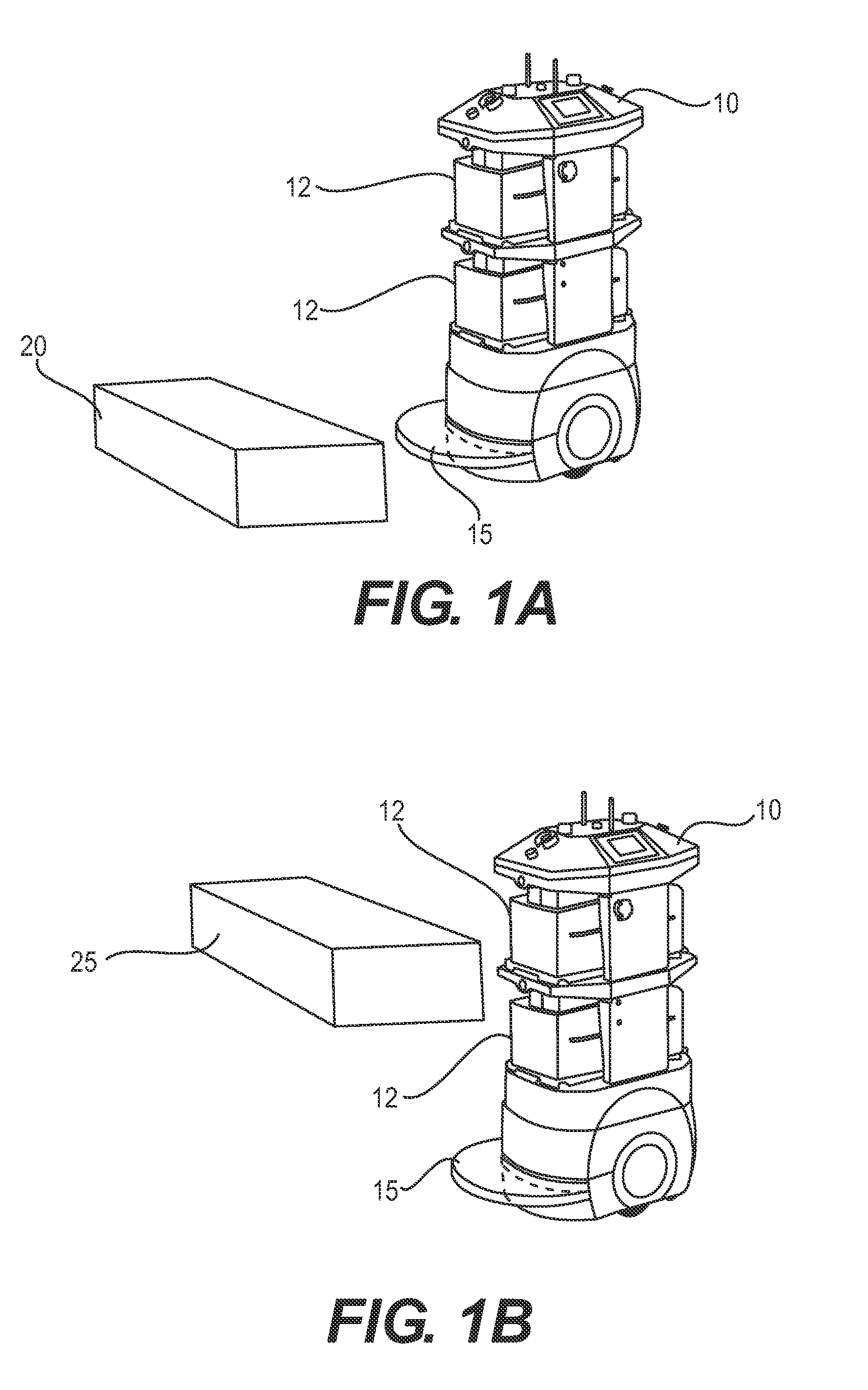
[0030]FIGS. 1A and 1B together illustrate, by way of non-limiting example, one of the disadvantages of conventional laser-based obstacle avoidance systems for mobile robots. As shown in FIGS. 1A and 1B, mobile robot 10 is equipped with a horizontally-oriented scanning laser (not shown), which emits laser light rays 15 that fan out in front of the robot in a substantially horizontal plane that is roughly parallel to the floor or other surface upon which the mobile robot travels. When mobile robot 10 approaches an obstacle that is resting on the floor of the physical environment, or very near the floor, such as obstacle 20 in FIG. 1A, the laser light rays 15 strike the obstacle 20 and are reflected back to the mobile robot 10. Sensors in the laser detect and process the reflections, thereby informing the mobile robot 10 that there is an obstacle 20 in its path that needs to be avoided. Thus, the obstacle avoidance and locomotion controllers on board mobile robot 10, if any, cause mobi...


PUM


Abstract

Embodiments of the present invention provide methods and systems for ensuring that mobile robots are able to detect and avoid positive obstacles in a physical environment that are typically hard to detect because the obstacles do not exist in the same plane or planes as the mobile robot's horizontally-oriented obstacle detecting lasers. Embodiments of the present invention also help to ensure that mobile robots are able to detect and avoid driving into negative obstacles, such as gaps or holes in the floor, or a flight of stairs. Thus, the invention provides positive and negative obstacle avoidance systems for mobile robots.

Description

CROSS-REFERENCE TO RELATED APPLICATIONS[0001]This Application is the U.S. National Stage entry of International Application No. PCT / US2013 / 023154, filed on Jan. 25, 2013 and which claimed priority to U.S. Provisional Application No. 61 / 590,806 filed on Jan. 25, 2012 and U.S. Provisional Application No. 61 / 596,685 filed on Feb. 8, 2012. The entire contents of International Application No. PCT / US2013 / 023154 and U.S. Provisional Application Nos. 61 / 590,806 and 61 / 596,685 are incorporated herein by reference.FIELD OF ART[0002]This invention generally relates to mobile robots. More specifically, the invention is directed to systems and methods for detecting positive and negative obstacles in physical environments through which mobile robots move and preventing the mobile robots from driving into those obstacles.BACKGROUND ART[0003]Mobile robots, including autonomously-navigating mobile robots, inertially-guided robots, remote-controlled mobile robots, and robots guided by laser targeting...

Claims


Application Information

Patent Timeline
Patent Type & Authority Patents(United States)
IPC IPC(8): G05B15/00G05B19/00G05B19/18G01S13/88
CPCG06N3/008B25J9/1676G05D1/024G05D1/0274G05B19/4061Y10S901/01G05B2219/39082Y10S901/50G05B2219/40202Y10S901/46
Inventor LAFARY, MATTHEWPAUL, GEORGE
Owner ORMON CORP
Why Eureka
Try Eureka