Railroad car wheel truck

a technology for wheel trucks and rail roads, applied in the field of wheel trucks, can solve problems such as lowering the dynamic performance of wheel trucks, and achieve the effects of improving the dynamic performance, high diamond resistant rigidity, and good dynamic performan

Active Publication Date: 2014-04-08
CRRC YANGTZE CO LTD
View PDF26 Cites 2 Cited by
  • Summary
  • Abstract
  • Description
  • Claims
  • Application Information

AI Technical Summary

Benefits of technology

[0010]In view of the above-described problems, it is one objective of the invention to provide a wheel truck that has a simple structure, low production and maintenance costs, superb dynamic performance for crossing curved tracks, and meets high requirements of the diamond resistant rigidity for the speed-raising trains.
[0013]In a class of this embodiment, a width of the wedge is L=200-600 mm, which is at least 1.3 times longer than the width of the conventional wedge having a variable friction. The wedge having a variable friction herein means that a wedge is disposed on a damping spring which is arranged in a square box in a center of a side frame, the damping friction exerted on the wedge changes in proportion to the variable vertical load exerted on the bolster assembly. The width design of the wedge not only increases the torque arm length of the wedge to resist the diamond deformation between the bolster assembly and the side frame assembly, but also increases the contact area between the primary friction surface and the column surface of the side frame assembly, and the contract surface between the secondary friction surface and the inclined surface of the bolster assembly. Thus, the diamond resistant rigidity between the bolster assembly and the side frame assembly is further improved.
[0014]In a class of this embodiment, a mechanical property of the damping spring meets the following formula: K1×ctgα=K×C / 2μ; K1 represents a rigidity of the damping spring; K represents a total rigidity of the spring suspension device; C represents a relative friction coefficient of the railroad freight car wheel truck and ranges from 0.05 to 0.15; and μ represents a friction coefficient of the primary friction surface. As the rigidity K1 of the damping spring is inversely proportional to ctga of the wedge, K1 can be adjusted according to the value of the angle α, thereby maintaining a suitable friction damping force, and preventing frictions from being too large during movements in vertical and horizontal directions.
[0016]First of all, the freight care wheel truck of the invention employs a wedge having a small vertex angle, which not only assures a free movement of the wedge when the bolster moves in a vertical direction, but also limits the wedge from moving when the bolster moves in a horizontal direction. Thus, the wheel truck has a high diamond resistant rigidity and good dynamic performance even without a cross supporting device or a spring plank. Furthermore, the design of the width of the wedge which is 1.3 times longer than that of the conventional wedges also improves the diamond resistant rigidity and the dynamic performance, thereby highly improving the critical speed of the freight car, the capacity of curved track crossing, and the running performance. Finally, the freight car wheel truck has a simple structure, light weight, and low production and maintenance costs, which is applicable to the new railroad freight car having a running speed of 120 km / h, and meets the requirements of the diamond resistant rigidity for the speed-raising trains.

Problems solved by technology

Supposing that, the value of the angle α is too small and approximates to the friction angle of the primary friction of the wedge, the wedge is apt to be self-limited once the bolster assembly moves downwards relative to the side frame assembly, thereby lowering the dynamic performance of the wheel truck.

Method used


Image

  • Railroad car wheel truck
  • Railroad car wheel truck
  • Railroad car wheel truck

Examples


Embodiment Construction

[0023]To further illustrate the invention, experiments detailing a wheel truck are described below. It should be noted that the following examples are intended to describe and not to limit the invention.

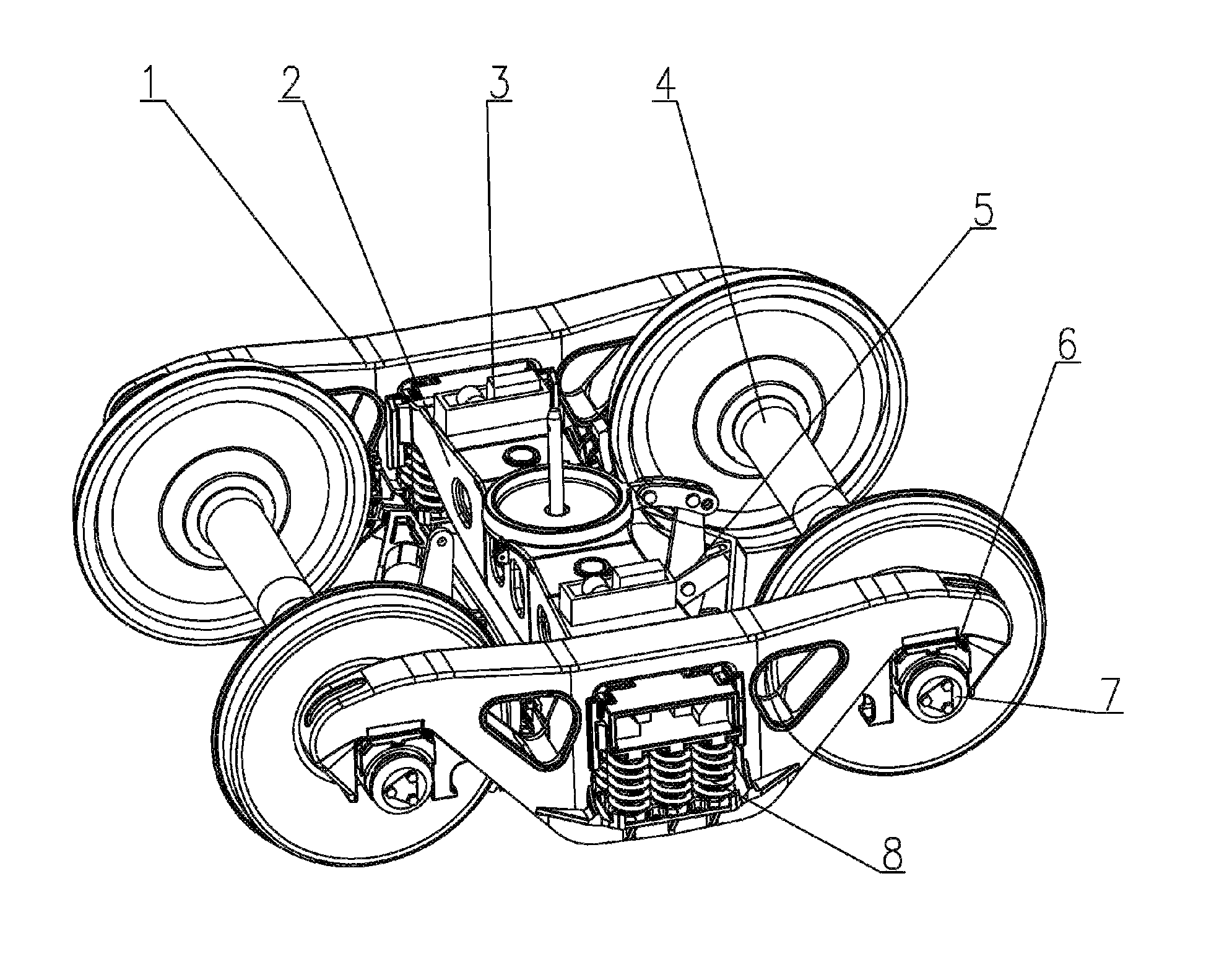
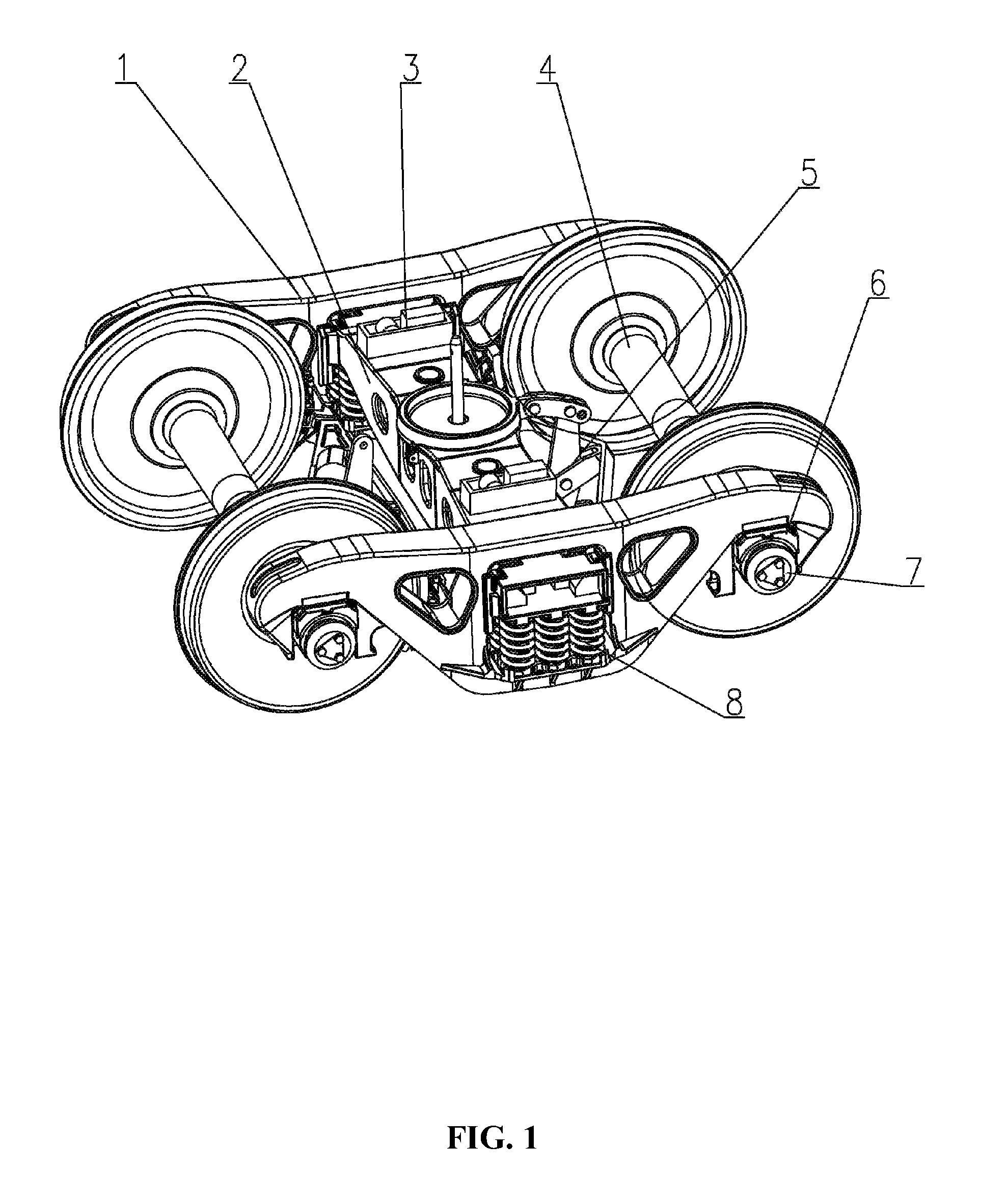
[0024]As shown in FIG. 1, a wheel truck having a high diamond resistant rigidity comprises a front wheel pair assembly 4 and a rear wheel pair assembly 4, two side frame assemblies 1, a bolster assembly 2, two spring suspension devices 8, two side pedestals 3, and a basic braking device 5. The wheel pair assembly 4 comprises bearing assemblies 7 on two ends. The side frame assemblies 1 comprise journal-box guides on two ends, and the journal-box guides are disposed on the bearing assemblies 7 via roller bearing adapters 6. Two ends of the bolster assembly 2 are respectively disposed in the spring suspension devices 8 which are disposed within square boxes in the center of the side frame assemblies 1.

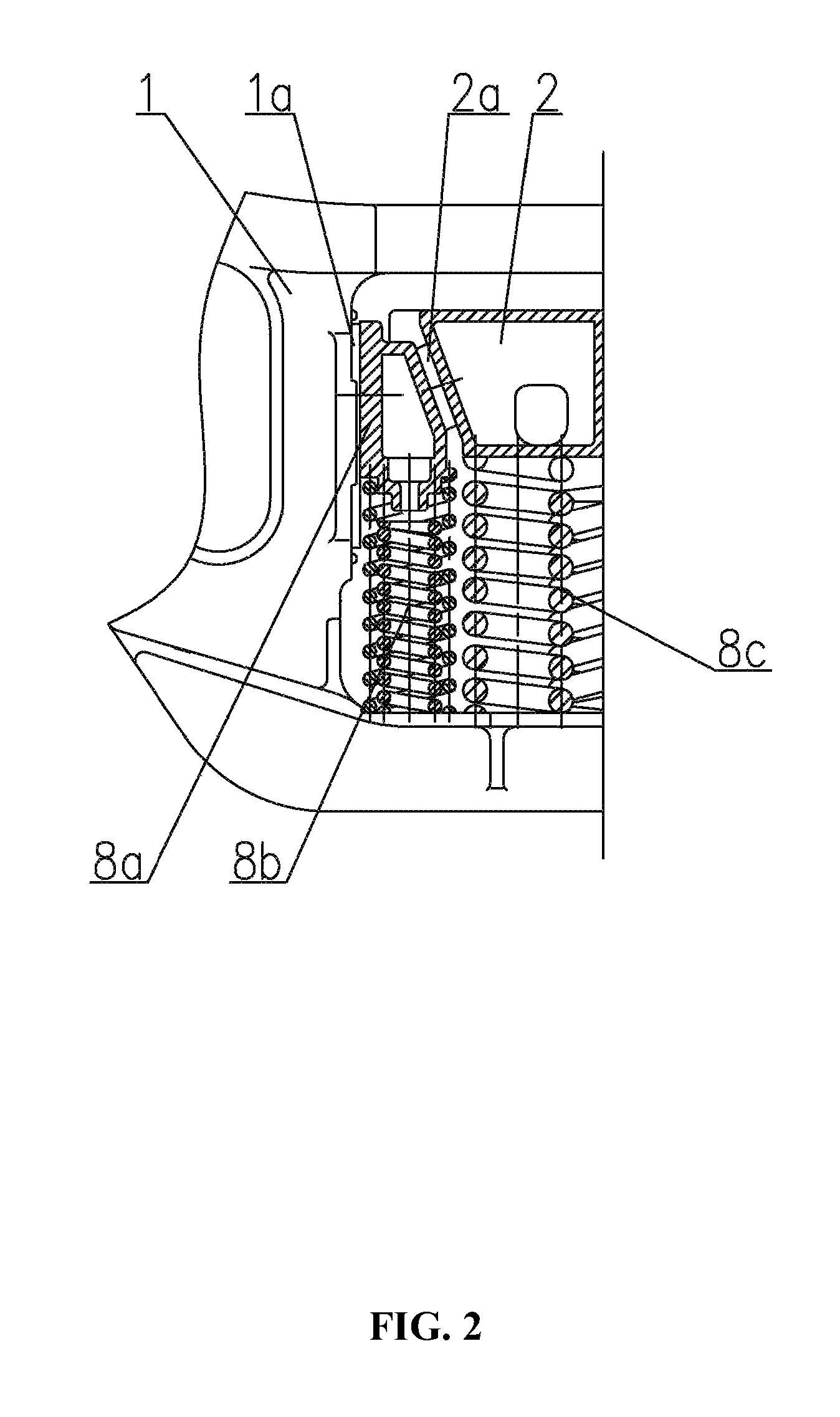
[0025]As shown in FIG. 2, the spring suspension devices 8 comprise a bearing spring u...


PUM


Abstract

A wheel truck, including: a front wheel pair assembly and a rear wheel pair assembly, two side frame assemblies, two spring suspension devices, and a bolster assembly. The spring suspension devices include a bearing spring unit, a damping spring, and a wedge. The wedge includes a primary friction surface and a secondary friction surface. The primary friction surface is attached to a column surface of the side frame assembly. The secondary friction surface is attached to an inclined surface of the bolster assembly. The wedge has the following structure parameters: α=16-30°, and μ<tgα<μ+μ1, in which a represents an included angle between the secondary friction surface and a vertical plane, μ represents a friction coefficient of the primary friction surface, and μ1 represents a friction coefficient of the secondary friction surface.

Description

CROSS-REFERENCE TO RELATED APPLICATIONS[0001]This application is a continuation-in-part of International Patent Application No. PCT / CN2010 / 079594 with an international filing date of Dec. 9, 2010, designating the United States, now pending, and further claims priority benefits to Chinese Patent Application No. 201010162226.3 filed Apr. 27, 2010. The contents of all of the aforementioned applications, including any intervening amendments thereto, are incorporated herein by reference. Inquiries from the public to applicants or assignees concerning this document or the related applications should be directed to: Matthias Scholl P.C., Attn.: Dr. Matthias Scholl Esq., 14781 Memorial Drive, Suite 1319, Houston, Tex. 77079.BACKGROUND OF THE INVENTION[0002]1. Field of the Invention[0003]The invention relates to a wheel truck, and more particularly to a railroad freight car wheel truck.[0004]2. Description of the Related Art[0005]As a critical part of a freight car, a typical railroad freigh...

Claims


Application Information

Patent Timeline
Patent Type & Authority Patents(United States)
IPC IPC(8): B61F3/00
CPCB61F5/122
Inventor SUN, MINGDAOXU, YONGWANG, BAOLEILI, YONGJIANG
Owner CRRC YANGTZE CO LTD
Why Eureka
Try Eureka