Vehicle body structure with body reinforcement behind the second row of seats

a vehicle body and seat technology, applied in the direction of roofs, transportation and packaging, vehicle arrangements, etc., can solve the problems of complex installation and production of all beam assembly arrangements described above as related art, and achieve the effects of simple corner reinforcement, light weight, and slight wall thickness

Active Publication Date: 2014-04-08
AUDI AG
View PDF50 Cites 12 Cited by
  • Summary
  • Abstract
  • Description
  • Claims
  • Application Information

AI Technical Summary

Benefits of technology

[0015]The profiled box formed as described above in a cast aluminum beam shell member provides in conjunction with the indicated connection and joining techniques a particularly simple corner reinforcement which can be produced by casting in a cost-efficient manner, with the shell member also producible with reinforcing ribs in a particularly weight-beneficial manner and with relatively slight wall thicknesses and the required stiffness.
[0016]In addition, weight can be reduced while preventing contact corrosions by also producing the floor crossbeam or a floor crossbeam shell member, and the respective vertical side beam or a vertical side beam shell member, from aluminum sheet. The beam connections with the corner r...

Problems solved by technology

In addition, all beam assembly arrangements described above as related art are very com...

Method used


Image

  • Vehicle body structure with body reinforcement behind the second row of seats
  • Vehicle body structure with body reinforcement behind the second row of seats
  • Vehicle body structure with body reinforcement behind the second row of seats

Examples


Embodiment Construction

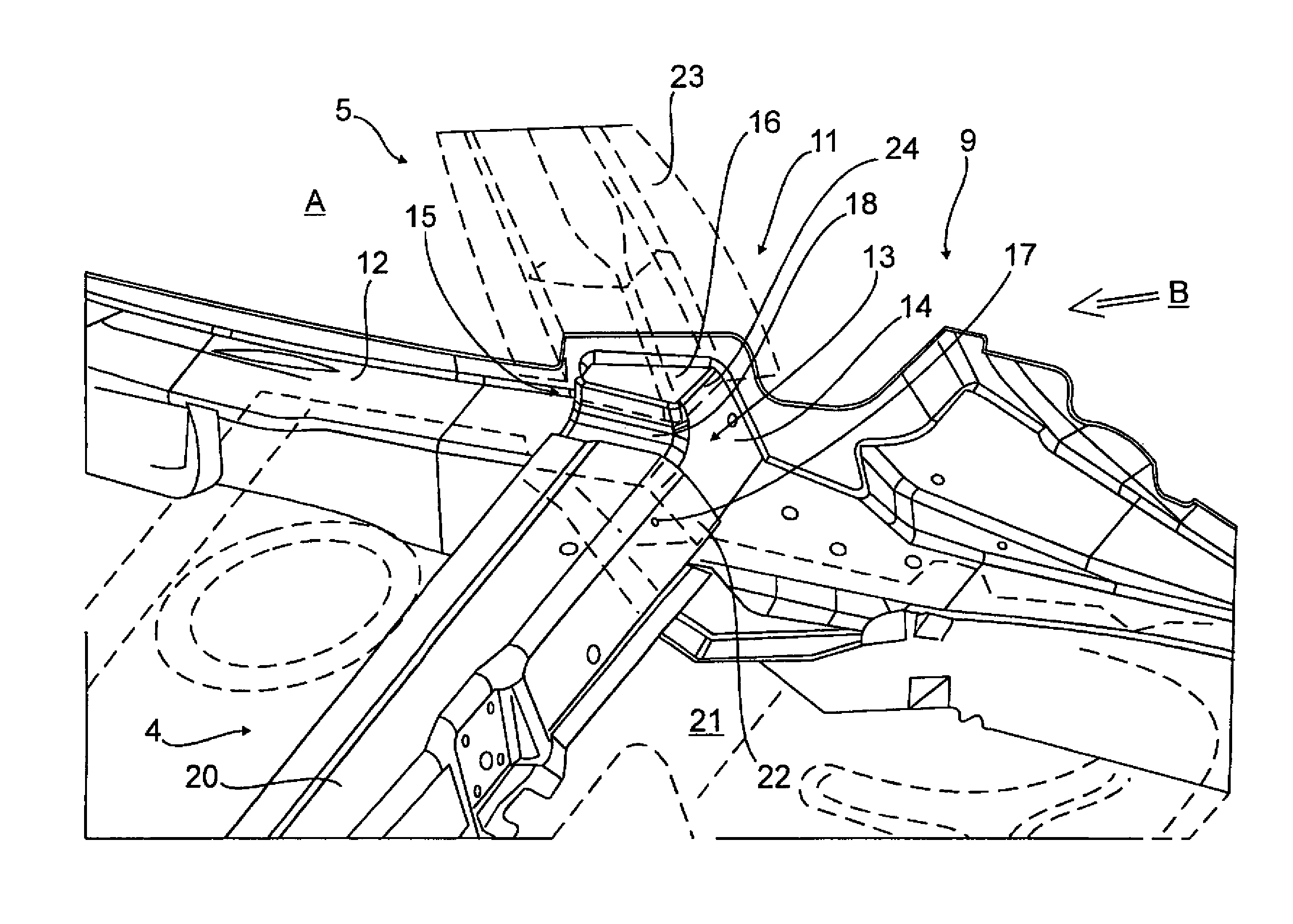
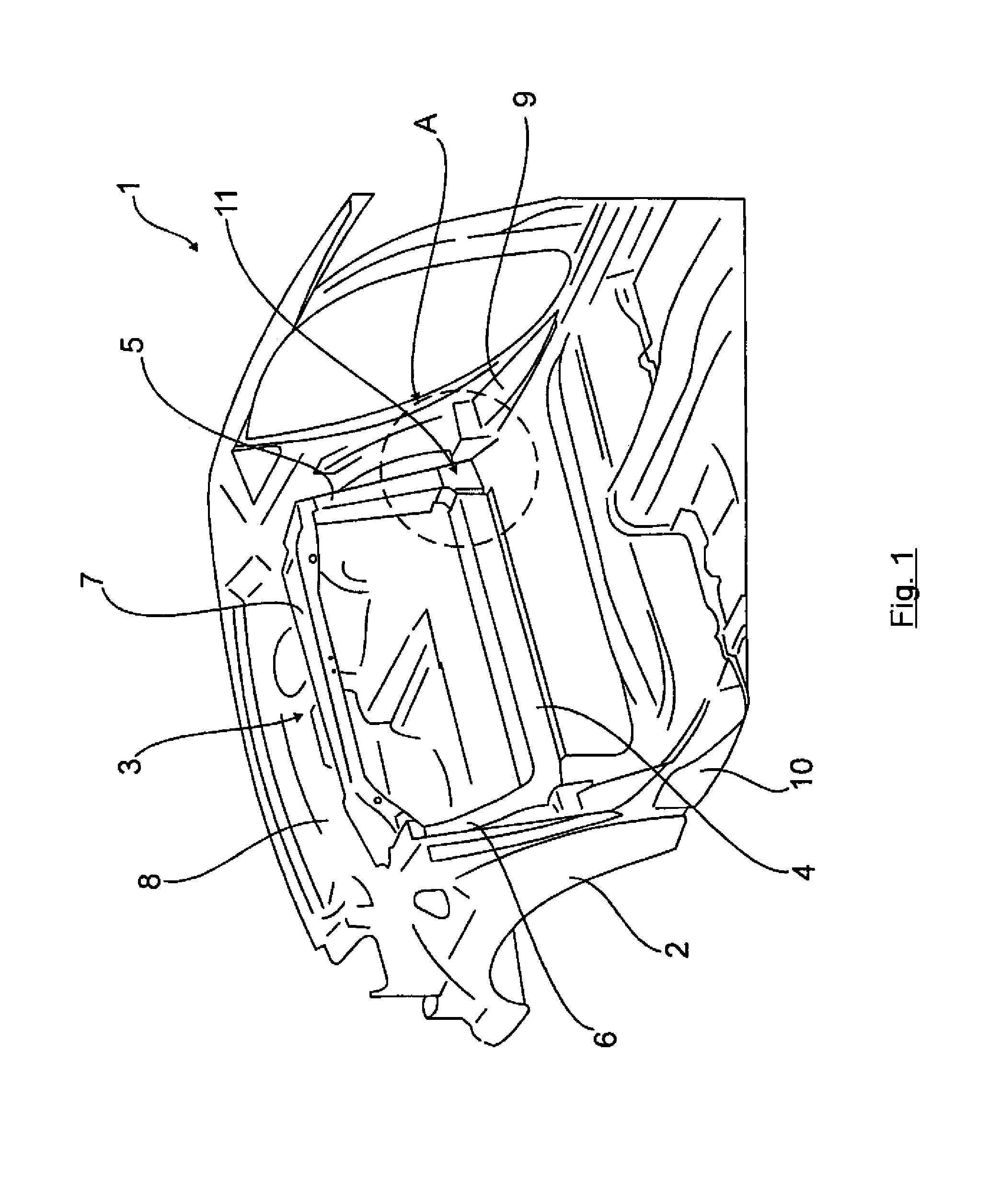
[0024]FIG. 1 shows the rearward area of part of a body 1 for a sedan with foldable rear bench seat for increasing the trunk space. A torsion ring 3 is positioned in the area between opposite wheel wells 2 roughly in a vertical transverse plane for stiffening the body 1. This torsion ring 3 includes a floor crossbeam 4, a left-side vertical side beam 5, and a right-side vertical side beam 6 as well as an upper crossbeam 7 in the area of and at level with a rear window shelf 8 for connecting the vertical side beams 5, 6. In addition, the torsion ring 3 is connected at the floor-proximal corner regions to a left-side longitudinal side beam 9 and a right-side longitudinal side beam 10 at nodal points 11, respectively. The left-side nodal point 11, according to the area A in FIG. 1, is illustrated in detail with reference to FIGS. 2 and 3.

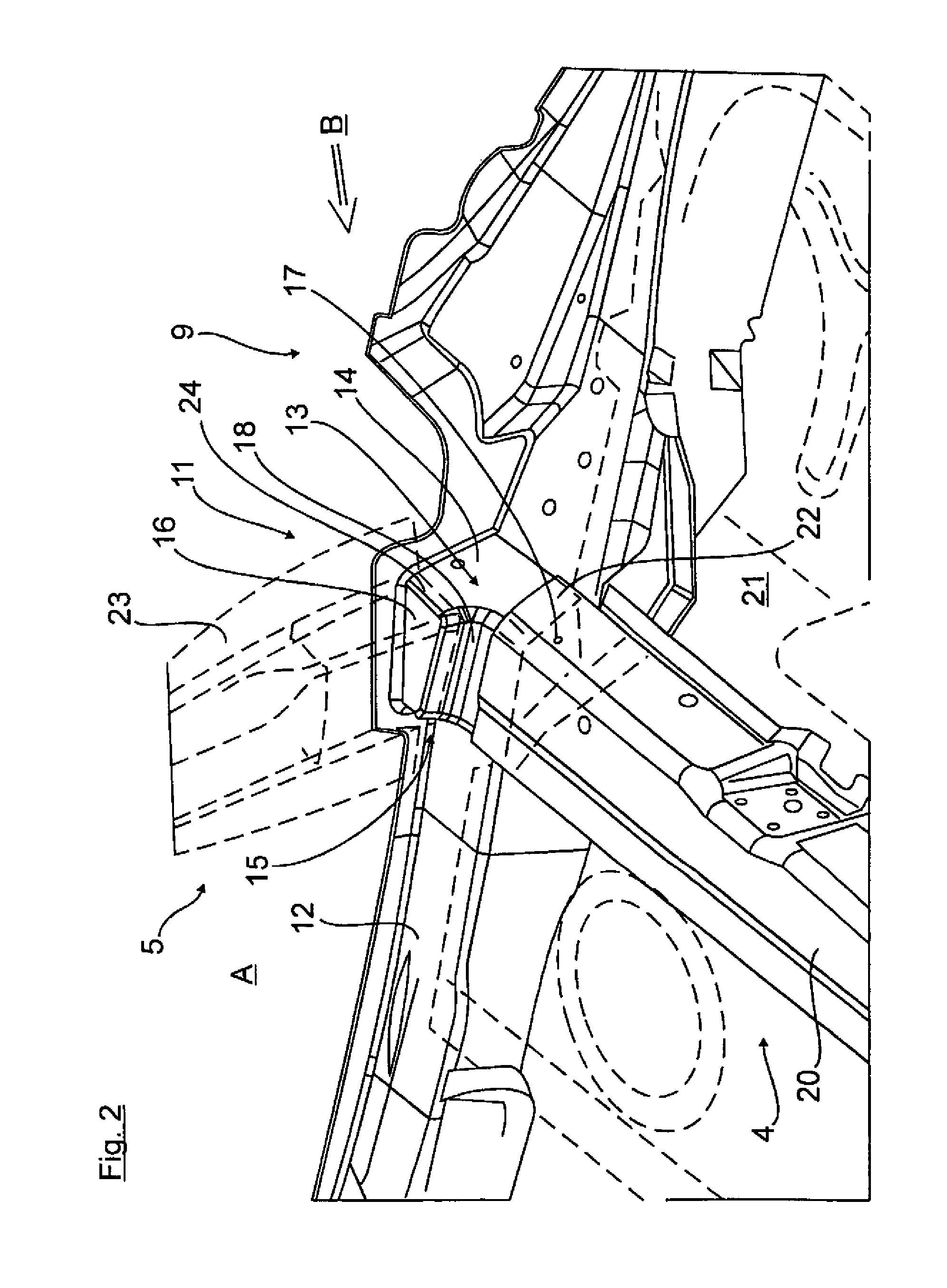
[0025]FIG. 2 involves hereby an enlarged view of the area A of FIG. 1, and FIG. 3 involves a side bottom view upon the object of FIG. 2, with a viewing...


PUM


Abstract

The invention relates to a vehicle body structure having a body reinforcement behind the second row of seats, the body reinforcement including a beam assembly which is formed from two opposite longitudinal side beams (9, 10), a floor crossbeam (4) and two vertical side beams (5, 6), of which in each case a left-side longitudinal side beam (9), an associated end of the floor crossbeam (4) and a left-side vertical side beam (5) are connected at a left-side nodal point (11) and, correspondingly, the second longitudinal side beam (10) is connected to the other end of the floor crossbeam (4) and the second vertical side beam (10) at a right-side nodal point, and, at the two nodal points, corner reinforcements being fitted for increased stiffening in the transverse plane of the floor crossbeam (4) and the vertical side beams (5, 6). According to the invention, the longitudinal side beams (9, 10) are cast aluminum longitudinal side beams, on which in each case at the nodal point (11) a corner reinforcement is formed and integrated as an corner reinforcing profile (13) made of uniform material and projecting in the manner of a box, wherein the associated vertical side beam (5, 6) is connected to the corner reinforcing profile (13) at the top on one hand, and is connected to the floor crossbeam (4) laterally on the other hand.

Description

CROSS-REFERENCES TO RELATED APPLICATIONS[0001]This application is the U.S. National Stage of International Application No. PCT / EP2010 / 005887, filed Sep. 27, 2010, which designated the United States and has been published as International Publication No. WO 2001 / 03 / 8877 and which claims the priority of German Patent Application, Ser. No. 10 2009 047 810.8, filed Sep. 30, 2009, pursuant to 35 U.S.C. 119(a)-(d).BACKGROUND OF THE INVENTION[0002]The invention relates to a vehicle body structure with a body reinforcement behind the second row of seats.[0003]Such a generic body reinforcement is known from DE 10 2004 014 664 A1 and includes a beam assembly which is formed from two opposing longitudinal side beams, a floor crossbeam, and two vertical side beams. A left-side longitudinal side beam, an associated left end of the floor crossbeam, and a left-side vertical side beam are respectively connected to a left-side nodal point. Likewise, the second right-side longitudinal beam is connect...

Claims


Application Information

Patent Timeline
IPC IPC(8): B62D25/08
CPCB62D25/2027B62D27/023B62D25/025B62D25/2036B62D29/008B62D25/087
Inventor KUHL, SONKECARLE, KLAUS-DIETERURBAN, TOBIASTHAYSEN, OLIVER
Owner AUDI AG
Why Eureka
Try Eureka