Functionally graded polycrystalline diamond insert

a technology of diamond inserts and polycrystalline diamonds, applied in the field of rotary cone bits, can solve the problems of reducing the hardness and wear resistance of pcd materials, limiting the flexibility of being able to provide pcd coatings with desired hardness, wear resistance and toughness levels, and reducing the toughness of pcd materials, so as to achieve the effect of prolonging the service life and improving the degree of thermal stability during operation

Active Publication Date: 2014-04-15
SMITH INT INC
View PDF125 Cites 14 Cited by
  • Summary
  • Abstract
  • Description
  • Claims
  • Application Information

AI Technical Summary

Benefits of technology

[0012]PCD inserts constructed in this manner provide a desired combination / balance of wear resistance and toughness using a reduced diamond body outer layer thickness. Further, the gradient change of metal content and diamond content within the diamond body operates to reduce or eliminate the existence of residual stress concentrations within the construction to thereby provide an extended service life. Further still, the combined construction of such FG-PCD layers with the transition layer or layers operates to provide an improved degree of thermal stability during operation when compared to conventional PCD inserts, thereby effectively extending service life.

Problems solved by technology

However, while higher metal binder content typically increases the toughness of the resulting PCD material, higher metal content also decreases the PCD material hardness and wear resistance, thus limiting the flexibility of being able to provide PCD coatings having desired levels of hardness, wear resistance and toughness.
Additionally, when variables are selected to increase the hardness or wear resistance of the PCD material, typically brittleness also increases, thereby reducing the toughness of the PCD material.
However, carbide content manipulation does not always promote the best transition between adjacent PCD insert layers, permitting discrete interfaces to exist between the layers which can promote unwanted stress concentrations.
The existence of these discrete interfaces, and the resulting stress concentrations produced therefrom, can cause premature failure of the PCD insert by delamination along the layer-to-layer interfaces.

Method used


Image

  • Functionally graded polycrystalline diamond insert
  • Functionally graded polycrystalline diamond insert
  • Functionally graded polycrystalline diamond insert

Examples


Embodiment Construction

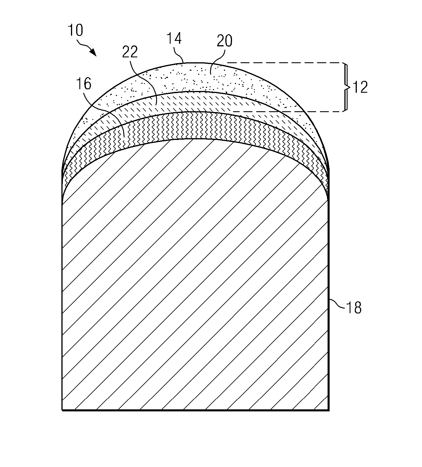
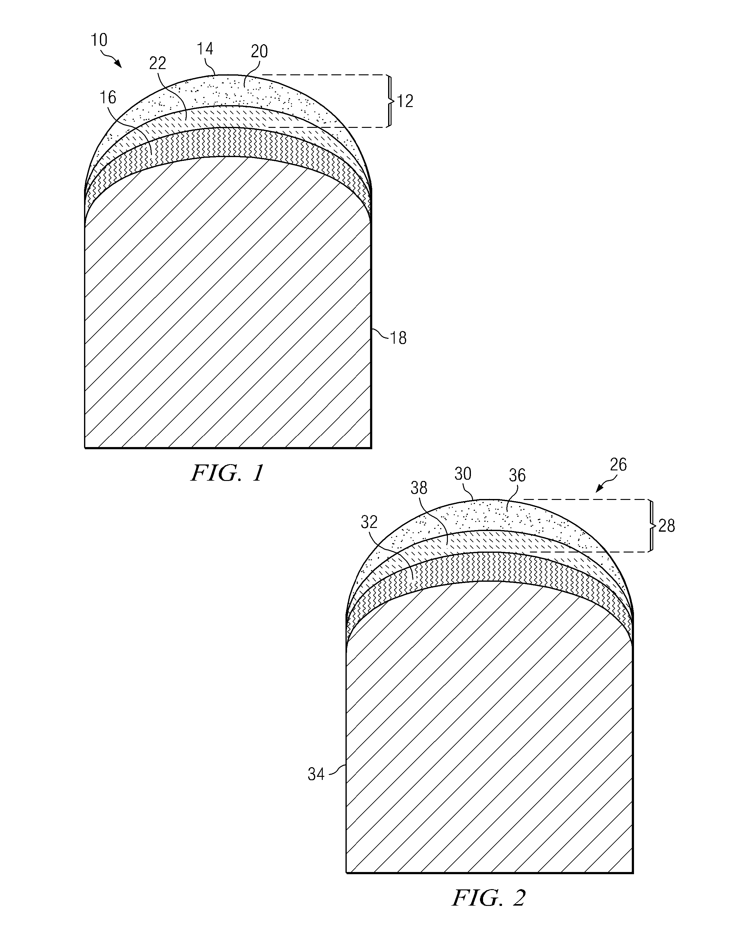
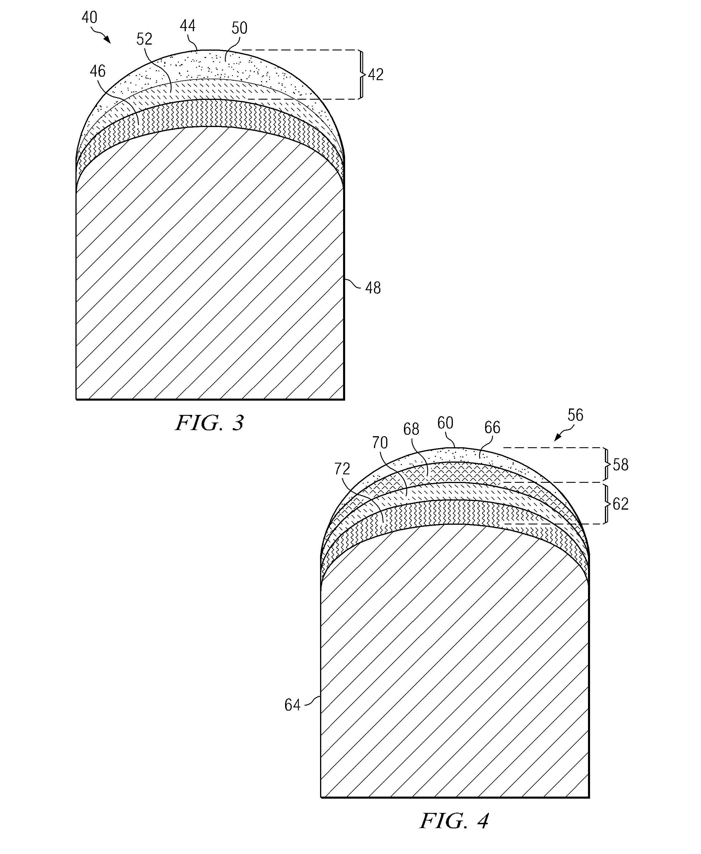
[0023]As used in this specification, the term polycrystalline diamond, along with its abbreviation “PCD,” refers to the material produced by subjecting individual diamond crystals or grains sufficiently high pressure and high temperature conditions in the presence of a metal solvent catalyst material or metal binder material that intercrystalline bonding occurs between adjacent diamond crystals. A characteristic of PCD is that the diamond crystals bonded to each other to form a rigid body having a material microstructure comprising a matrix phase of intercrystalline bonded diamond with the metal binder dispersed within interstitial regions within the matrix phase.

[0024]PCD inserts of this invention generally comprise a functionally-graded PCD (FG-PCD) material that can be provided as two or more layers comprising a decreasing diamond content moving away from an outer or working surface of the insert towards a substrate. The decreasing diamond content within the FG-PCD material is ac...


PUM

PropertyMeasurementUnit
thicknessaaaaaaaaaa
thicknessaaaaaaaaaa
thicknessaaaaaaaaaa

Abstract

PCD inserts comprise a PCD body having multiple FG-PCD regions with decreasing diamond content moving from a body outer surface to a metallic substrate. The diamond content changes in gradient fashion by changing metal binder content. A region adjacent the outer surface comprises 5 to 20 percent by weight metal binder, and a region remote from the surface comprises 15 to 40 percent by weight metal binder. One or more transition regions are interposed between the PCD body and substrate. The transition region comprises PCD, binder metal, and a carbide, comprises a metal binder content less than that present in the PCD body region positioned next to it.

Description

CROSS-REFERENCE TO RELATED APPLICATIONS[0001]This application claims priority to U.S. Provisional Application No. 61 / 232,151, filed Aug. 7, 2009, which is hereby incorporated by reference in its entirety.BACKGROUND OF THE INVENTION[0002]1. Field of the Invention[0003]This invention relates to rotary cone bits used for subterranean drilling and, more particularly, to inserts used with rotary cone bits that are specially engineered having a functionally graded polycrystalline diamond microstructure to provide improved elastic properties, mechanical properties and / or thermal properties when compared to conventional polycrystalline diamond inserts.[0004]2. Background Art[0005]Polycrystalline diamond (PCD) materials known in the art are formed from diamond grains or crystals and a ductile metal binder and are synthesized by high temperature / high pressure processes. Such material is well known for its mechanical properties of wear resistance, making it a popular material choice for use in...

Claims


Application Information

Patent Timeline
Patent Type & Authority Patents(United States)
IPC IPC(8): E21B10/46E21B10/36E21B10/567
CPCE21B10/5735E21B10/46B22F2999/00B22F7/08E21B10/567Y10T428/30E21B10/5673C22C26/00B22F2207/03
Inventor FANG, YIBELLIN, FEDERICOSTEWART, MICHAELMOURIK, NEPHI ACARIVEAU, PETER T
Owner SMITH INT INC
Why Eureka
Try Eureka