Dual-electrode traveling wave optical phase shifters and methods

a traveling wave and optical phase shifter technology, applied in non-linear optics, instruments, optics, etc., can solve the problems of high required driving voltage, inability to increase the effective modulation length beyond the limit, and the required driving voltage cannot be increased beyond the limit, so as to reduce the thickness of the buffer layer, and improve the phase matching

Inactive Publication Date: 2006-08-22
II VI DELAWARE INC
View PDF14 Cites 14 Cited by
  • Summary
  • Abstract
  • Description
  • Claims
  • Application Information

AI Technical Summary

Benefits of technology

[0022]Optionally, a buffer layer is inserted between electrodes and a substrate to improve phase matching between an electrical signal and an optical signal. Advantageously, the present invention employing tri-electrodes or dual-electrodes allow for a better match of phase velocity and allow for a reduced buffer layer thickness that may be used between the optical and electrical waveguide.

Problems solved by technology

For 40 Gb / sec. modulation, one of the major challenges is to reduce the required driving voltage of the modulator, which is generally dictated by high electrode loss and the difficulties of generating high-voltage swing with semiconductors at this speed.
Due to bandwidth considerations, the effective modulation length cannot be increased beyond a limit and hence a driving voltage above a threshold is required to achieve a required optical modulation.
For high-speed communications systems transmitting at 10 Gb / sec or higher, the electrode loss is significant and typically leads to a very high required driving voltage.
Given the high loss and the limited voltage swing, it adds more complexity and cost to realize a practical communication system using such a modulator, if not impossible.
The under-driven modulator would lead to significant degradation of the modulated light signal and significantly limits its use to many communication systems.
However, it is difficult to realize due to phase matching required of the two stages of the electrode.
It does not provide an effective means to reduce the driving voltage.
However, it is difficult to realize due to the additional processes and the additional optical signal losses incurred by fabricating the ridge.
Moreover, the reduction of the driving voltage is very limited, which is about 20% typically.

Method used


Image

  • Dual-electrode traveling wave optical phase shifters and methods
  • Dual-electrode traveling wave optical phase shifters and methods
  • Dual-electrode traveling wave optical phase shifters and methods

Examples


first embodiment

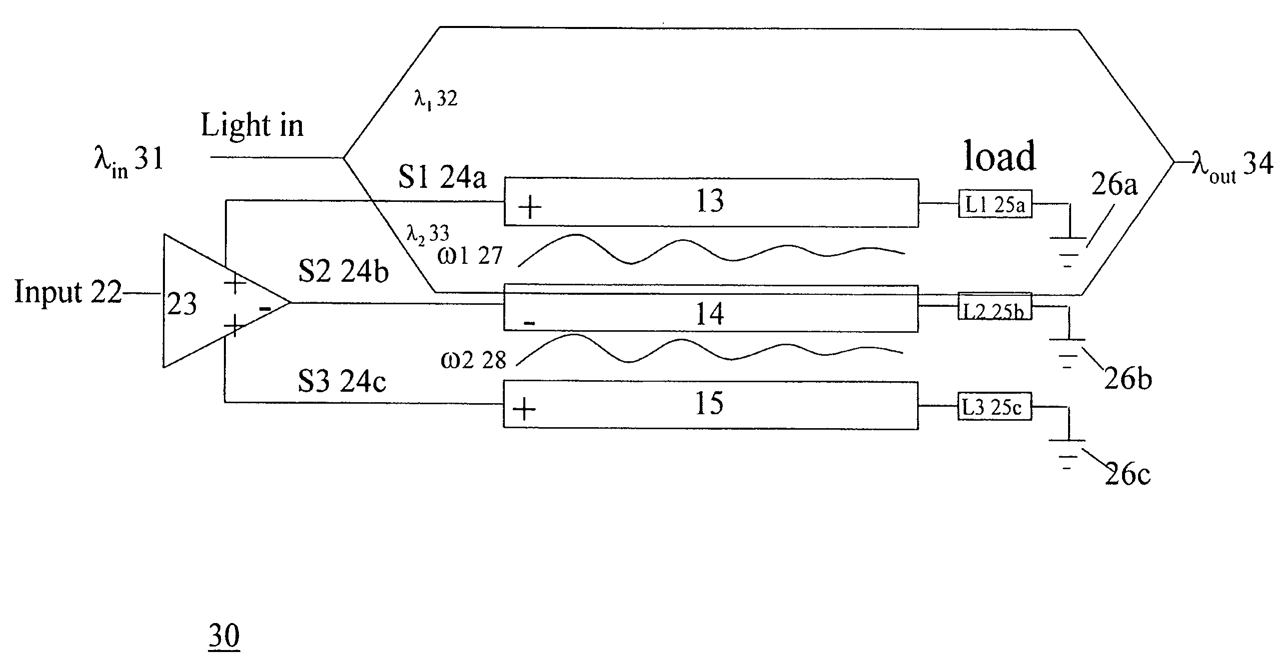
[0080]FIG. 8 is a circuit diagram illustrating two optical phase shifters 80 in constructing an optical switch, a modulator, or a Mach-Zehnder type interferometer. The two phase-shifters 80 has an upper phase shifter 81 and a lower optical phase shifter 70. The light signal input λin 82 is split into two paths, the λ1 83 and the λ2 84, which are re-combined to generate a the λout 85. In this embodiment, the light signal λ1 82 travels between a positive electrode 45b and a negative electrode 45c, while the light signal λ2 83 travels between the positive electrode 13 and the negative electrode 14. The amplifier 42 receives the input 41 and generates a first output to an amplifier 43, and a second output to the amplifier 23. The amplifier 43 receives then generates three electrical outputs through a transmission line S144a, a transmission line S244b, and a transmission line S344c. The transmission line S144a extends through a first electrode 45a to the load L1 or termination resistor 4...

second embodiment

[0081]FIG. 9 is a circuit diagram illustrating a two phase-shifters in constructing an optical switch, a modulator, or a Mach-Zehnder type interferometer. The light signal input λin 91 is split into two paths, the λ1 92 and the λ2 93, which are re-combined to generate a the λout 94. In this embodiment, the light signal λ1 82 travels between a negative electrode 45a and a positive electrode 45b, while the light signal λ2 83 travels between the negative electrode 14 and the positive electrode 15.

third embodiment

[0082]FIG. 10 is a circuit diagram illustrating two optical phase shifters 100 in constructing an optical switch, a modulator, or a Mach-Zehnder type interferometer. The light signal input λin 101 is split into two paths, the λ1102 and the λ2103, which are re-combined to generate a λout 104. In this embodiment, the light signal λ1102 travels between the negative electrode 45a and the positive electrode 45b, while the light signal λ2103 travels between the negative electrode 13 and the positive 15 electrode 14.


PUM

PropertyMeasurementUnit
thicknessaaaaaaaaaa
widthaaaaaaaaaa
polarityaaaaaaaaaa

Abstract

The invention discloses phase-shifters, modulators, and method that produces a smaller π by means of a field excitation using multiple electrodes. A negative signal is introduced that travels with the positive signal, which enhances the electric field significantly. The field enhancement is provided by the superposition of the fields accumulated from each electrode. A base or substrate material can be made from any compound having linear electro-optic properties, such as lithium niobate, lithium tantalite, potassium lithium niobate, potassium titanyl phosphate or gallium-arsenide. For lithium niobate, there are two possible orientations of electric field, z-cut orientation or x-cut orientation.

Description

CROSS REFERENCE TO RELATED APPLICATIONS[0001]This application relates to concurrently filed, co-pending application U.S. patent application Ser. No. 09 / 791,956, entitled “Tri-Electrode Traveling Wave Optical Phase Shifters and Methods” by Marc Hill et al., owned by the assignee of this application and incorporated herein by reference.[0002]This application relates to concurrently filed, co-pending application U.S. patent application Ser. No. 09 / 792,220, entitled “Tri-Electrode Traveling Wave Optical Modulators and Methods” by Marc Hill et al., owned by the assignee of this application and incorporated herein by reference.[0003]This application relates to concurrently filed, co-pending application U.S. patent application Ser. No. 09 / 792,222, entitled “Dual-Electrode Traveling Wave Optical Modulators and Methods” by Marc Hill et al., owned by the assignee of this application and incorporated herein by reference.BACKGROUND INFORMATION[0004]1. Field of the Invention[0005]The present inv...

Claims


Application Information

Patent Timeline
Patent Type & Authority Patents(United States)
IPC IPC(8): G02F1/035
CPCG02F1/225G02F2201/126
Inventor HILL, MARC E.KING, JONATHAN P.WU, HUI
Owner II VI DELAWARE INC
Why Eureka
Try Eureka