Cutting insert and cutting tool therefor

a cutting insert and indexing technology, applied in metal-working equipment, metal-working equipment, milling equipment, etc., can solve the problems of limited use of conventional clamping methods, shearing of clamping screws, and inability to cut inserts

Inactive Publication Date: 2014-04-15
ISCAR LTD
View PDF38 Cites 13 Cited by
  • Summary
  • Abstract
  • Description
  • Claims
  • Application Information

AI Technical Summary

Benefits of technology

[0084]In view of the described above, the cutting tool 20 according to the present invention may have advantage when incorporating the following features:
[0085]First, the second non-zero angle β that is formed between the side support surface 38 of the pocket 30 and the inclined base support surface 42 of the pocket 30 creates a radially inwardly directed force component 98 (see FIG. 11) that acts on the cutting insert 24 during machining, thus decreasing the shear force acting on the clamping screw 26, especially, at very high machining speeds. Thus, the clamping screw 26 firmly clamps the cutting insert 24 and more stable operation of the cutting tool 20 is obtained.

Problems solved by technology

When using such a rotary cutting tool at high speeds, however, stability problems arise due to a great magnitude of centrifugal forces created by the high rotational speed at which the rotary cutting tool operates.
Moreover, the centrifugal force can cause shearing of the clamping screw.
Due to these problems, use of conventional clamping methods is limited and it is unsatisfactory to rely exclusively upon a clamping screw to releasably secure the cutting insert to the holder or to a cassette.
Employing external clamps only aggravates the problem, since the added mass of the clamps creates even greater centrifugal forces, making the stability problems even worse.
However, this type of construction leads to very high levels of stress on the main body of the tool, especially, in the base region of the groove due to the notch effect.
However, such a clamping arrangement may create over-constrained clamping, which may cause equivocal positioning of the indexable insert in the tool body.

Method used


Image

  • Cutting insert and cutting tool therefor
  • Cutting insert and cutting tool therefor
  • Cutting insert and cutting tool therefor

Examples


first embodiment

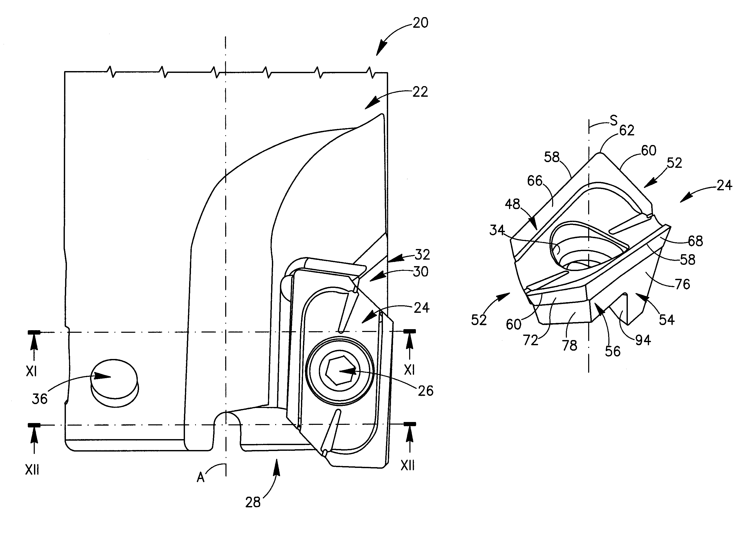
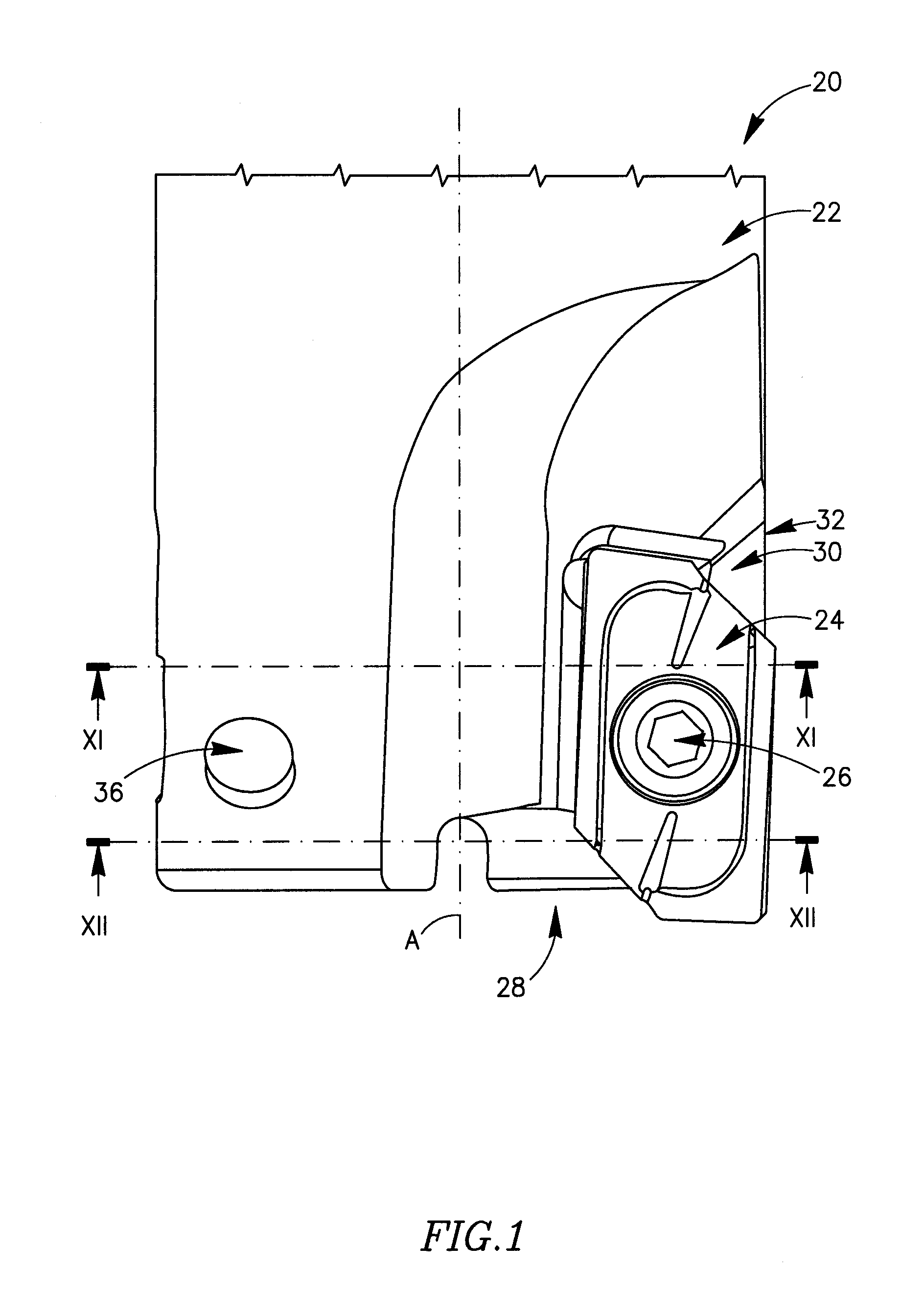
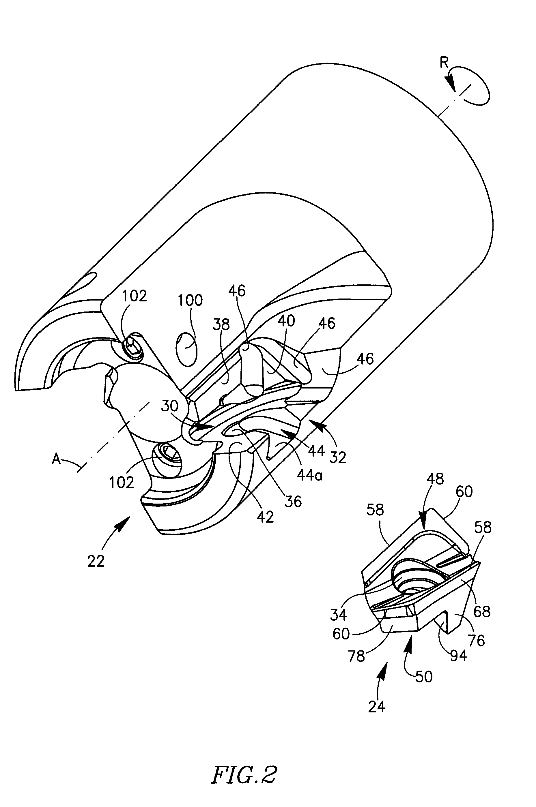
[0060]Attention is first drawn to FIGS. 1 to 12 showing a cutting tool 20 with a longitudinal axis A defining a front-to-rear direction and a direction of rotation R. The cutting tool 20 comprises a tool holder 22, two cutting inserts 24 and two clamping screws 26 in accordance with the present invention. The tool holder 22 has a front cutting portion 28. The front cutting portion 28 of the tool holder 22 has two pockets 30 formed at a perimeter 32 of the tool holder 22. However, other embodiments of the invention may have one, three or more pockets 30. Each of the pockets 30 opens tangentially forwardly and radially outwardly toward the perimeter 32. Since the two pockets 30 are identical, only one of them will be described.

[0061]A given cutting insert 24 is removably secured in the pocket 30 of the tool holder 22 by means of a clamping screw 26. The cutting insert 24 has a general shape of a hexagonal prism as seen in a top view and a bottom view of the cutting insert 24. In other...

second embodiment

[0077]In accordance with the present invention as shown in FIG. 13, the cutting insert 124 has only one base abutment plane 184 and thus, only one set of base abutment surfaces. As seen in FIG. 13, the base abutment plane 184 contains a major base abutment surface 180, it being understood that the base abutment plane 184 also contains a minor abutment surface (not shown in FIG. 13) not unlike minor abutment surface 82.

[0078]The lower surface 50 of the cutting insert 24 is further provided with a pair of intermediate surfaces 92 and a pair of transition surfaces 94 that join between the differently inclined first and second major base abutment surfaces 80, 86. As best seen in FIGS. 3 and 4, the transition surfaces 94 are directed transversely to the side abutment surfaces 76, and transversely to the first and second major base abutment surfaces 80, 86.

[0079]The upper surface 48 of the cutting insert 24 is provided with an optional arrangement of chip guiding means 96. Since the upper...


PUM

PropertyMeasurementUnit
angleaaaaaaaaaa
non-zero angleaaaaaaaaaa

Abstract

A cutting tool has at least one cutting insert seated therein. The cutting insert has a longitudinal axis, an upper surface, a lower surface and a peripheral surface that extends between the upper surface and the lower surface. At least a portion of an intersection between the upper surface and the peripheral surface constitutes a cutting edge. The lower surface has at least one set of base abutment surfaces, each set including at a least one major base abutment surface and at least one minor base abutment surface, the major and minor base abutment surfaces of a given set being spaced apart from one another along the longitudinal axis. When the lower surface has two such sets of base abutment surfaces, the major and minor base abutment surfaces of the first set are longitudinally displaced from the corresponding major and minor base abutment surfaces of the second set. Furthermore, the major and minor base abutment surfaces of the first set lie on a first base abutment plane while the major and minor base abutment surfaces of the second set lie on a second base abutment plane, the first and second base abutment planes forming a first non-zero angle therebetween.

Description

FIELD OF THE INVENTION[0001]The present invention relates to an indexable cutting insert and to a holder for such a cutting insert.BACKGROUND OF THE INVENTION[0002]Rotary cutting tools having holders and replaceable cutting inserts clamped therein by a clamping screw are known. When using such a rotary cutting tool at high speeds, however, stability problems arise due to a great magnitude of centrifugal forces created by the high rotational speed at which the rotary cutting tool operates. Moreover, the centrifugal force can cause shearing of the clamping screw. Due to these problems, use of conventional clamping methods is limited and it is unsatisfactory to rely exclusively upon a clamping screw to releasably secure the cutting insert to the holder or to a cassette. Employing external clamps only aggravates the problem, since the added mass of the clamps creates even greater centrifugal forces, making the stability problems even worse. Consequently, tools for high-speed machining r...

Claims


Application Information

Patent Timeline
Patent Type & Authority Patents(United States)
IPC IPC(8): B23C5/20
CPCB23C5/109B23C2210/168B23C2200/164B23C5/2221B23C2200/085B23C2210/0457B23C5/2213B23C2200/161B23C2200/284Y10T407/23Y10T407/1934Y10T407/1908Y10T407/1924Y10T407/1936Y10T407/192
Inventor SATRAN, AMIR
Owner ISCAR LTD
Why Eureka
Try Eureka