Further improvements to ankle-foot prosthesis and orthosis capable of automatic adaptation to sloped walking surfaces

a technology of automatic adaptation and ankle-foot prosthesis, which is applied in the field of improved ankle-foot prosthetic and orthotic systems, can solve the problems of compromising user's balance, affecting the stability of users' feet, and many currently available ankle-foot mechanisms that do not allow ankle motion, so as to prevent or reduce the likelihood of compromising users' balan

Active Publication Date: 2014-04-15
U S GOVERNMENT REPRESENTED BY THE DEPT OF VETERANS AFFAIRS
View PDF32 Cites 27 Cited by
  • Summary
  • Abstract
  • Description
  • Claims
  • Application Information

AI Technical Summary

Benefits of technology

[0013]The invention provides prosthetic and orthotic ankle-foot systems. The systems can be used by a human subject as a prosthesis or an orthosis to assist the user's gait and to prevent or reduce the likelihood of compromising the user's balance.
[0016]In another preferred embodiment, the torsion means is selected from the group consisting of a spring, a tunable spring, a clockwork spring, a piston, a damper, a bumper, and an elastomeric material. In another preferred embodiment the neutralizing element and the clutch are in-line. In another most preferred embodiment, the ankle system has a plantarflexion-dorsiflexion range of from between 80° plantarflexion to about 45° dorsiflexion. In another embodiment the ankle system allows a user to emulate normal gait. In an alternative embodiment, the ankle system allows a user to approximately emulate normal gait.
[0020]In another preferred embodiment, the improved adaptive ankle-foot orthosis is shaped and adapted for placement on at least one side of the biological ankle of the user or individual. In another preferred embodiment, the torsion means is selected from the group consisting of a spring, a tunable spring, a clockwork spring, a piston, a damper, a bumper, and an elastomeric material. In another preferred embodiment the neutralizing element and the clutch are in-line. In another most preferred embodiment, the ankle system has a plantarflexion-dorsiflexion range of from between 80° plantarflexion to about 45° dorsiflexion. In another embodiment the ankle system allows a user to emulate normal gait. In an alternative embodiment, the ankle system allows a user to approximately emulate normal gait.

Problems solved by technology

Many currently available prosthetic and orthotic ankle-foot mechanisms do not allow ankle motion.
However, problems can arise when walking on different terrain or when using shoes of different heel height.
However, this is not a simple task and one that does not happen automatically.
However, Koniuk's design does not appear to have energy storage and release properties, utilizes more sensing devices than the proposed design, and does not appear to give plantarflexion at late stance.
Current prosthetic ankle-foot mechanisms cannot automatically adapt to these conditions.
Recently, prosthetic devices have come onto the market that claim adaptability to sloped surfaces, yet these devices have their limitations.
In addition, the potential loss of energy from the damping of both the Echelon and Motionfoot may limit the ability of these prostheses to store and return energy to the user.
One of the limitations of the Proprio Foot is the timing of the adaptation.
In addition, the change is incremental, thus a significant change in slope could require several steps before full adaptation is achieved.
Another limitation of the Proprio Foot is its high cost.
Yet uneven surfaces with rapidly changing slope could result in a Proprio Foot adapted for a decline when the user steps onto an incline or vice versa.
Despite significant advances in prosthetic technology in recent years, commercially available lower limb prosthetic devices are as yet unable to provide biomimetic surface slope adaptation at the ankle on every step.

Method used


Image

  • Further improvements to ankle-foot prosthesis and orthosis capable of automatic adaptation to sloped walking surfaces
  • Further improvements to ankle-foot prosthesis and orthosis capable of automatic adaptation to sloped walking surfaces
  • Further improvements to ankle-foot prosthesis and orthosis capable of automatic adaptation to sloped walking surfaces

Examples


example i

Wrap Spring Clutch

[0131]The wrap spring clutch (FIG. 14, 14) comprised a spring coil (24) wrapped around a pair of equal diameter cylindrical arbors (19 and 20). The clutch used to lock out the low stiffness bumper in dorsiflexion needed to be small and light enough to fit within the reasonable dimensions of an anatomical ankle and foot, while still being capable of withstanding specific ankle moments of approximately 1.7 Nm·kg−1 (based on data from Hansen et al., 2004, “The Human Ankle During Walking: Implications for Design of Biomimetic Ankle Prostheses,” J. Biomech., 37(10): 1467-1474). For a 100 kg person, this would result in an ankle moment of 1700 Nm. During steady state walking, the clutch would be required to resist an external dorsiflexion moment only, thus a unidirectional clutch, such as the wrap spring clutch, would be acceptable, although other clutch systems may be considered.

[0132]Wrap spring clutch mechanisms have been used in other rehabilitation applications due ...

example ii

Adaptable Ankle

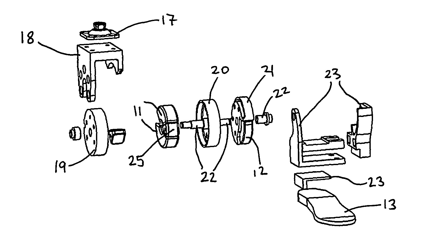
[0134]The adaptable ankle model presented in FIGS. 10C and D comprised three structures, shown assembled separately in FIG. 12 with non-structural parts removed. The shank structure (FIG. 12 A and white structures in FIG. 10) interfaced the adaptable ankle with the subject's socket and transferred moments to the driving arbor of the wrap spring clutch. The intermediate structure (FIG. 12B and gray structures in FIG. 10) received moments from the driven arbor of the wrap spring clutch, formed a track within which the left side of the shank structure rested, and applied forces to the high stiffness bumper. The foot structure (FIG. 12C and black structures in FIG. 10) supported the shaft about which all structures rotated, supported the high stiffness bumper, and held the footplate.

[0135]Between the intermediate structure and the foot structure rested the high stiffness bumper (FIG. 13). It was made from nominally 90 Shore A durometer polyurethane rubber (samples measure...

example iii

Testing

[0139]The adaptable ankle prototype was tested mechanically as well as on human subjects. The mechanical fatigue testing was performed based on the ISO 10328 cyclic test standards for prosthetic foot and ankle systems.

[0140]The cyclic fatigue testing was performed using a custom-built apparatus that applied separate heel and forefoot loads produced by pneumatic pistons. The adaptable ankle was tested to 100,000 cycles at the P4 load level, based on gait parameters for persons with body masses of 60-80 kg or 130-175 lb. The procedure was modified to account for the adaptable ankle prototype's unique function.

[0141]Results from the mechanical testing indicated that the central coil of the clutch spring, the coil which transitions from one arbor to the other, was causing damage that eroded material from the arbor rims to a depth of 0.51 mm). No other significant wear was observed. The clutch continued to hold proof test forces after cyclic testing.

[0142]The human subject testing...


PUM


Abstract

The present invention relates to an improved system for use in rehabilitation and / or physical therapy for the treatment of injury or disease to the lower limbs or extremities. The system can enable an amputee to proceed over any inclined or declined surface without overbalancing. The system is mechanically passive in that it does not utilize motors, force generating devices, batteries, or powered sources that may add undesirable weight or mass and that may require recharging. In particular the system is self-adapting to adjust the torque moment depending upon the motion, the extent of inclination, and the surface topography. An additional advantage of the improvement is that the system can be light and may also be simple to manufacture.

Description

[0001]The present application claims priority to U.S. Provisional Patent Application Ser. No. 61 / 461,703 entitled “Further Improvements to Passive Ankle-Foot Prosthesis Capable of Automatic Adaptation to Sloped Walking Surfaces and Methods of Use”, filed 20 Jan. 2011, which is herein incorporated by reference in its entirety for all purposes.[0002]This invention was made with government support under GM079300 awarded by National Institute of Health and H133E080009 awarded by the Department of Education (NIDDR). The government has certain rights in the invention.TECHNICAL FIELD[0003]The inventions relate to improved ankle-foot prosthetic and orthotic systems and methods of use. In particular the prosthetic or orthotic systems comprise an ankle unit that, in combination with other mechanical elements of prosthetic or orthotic systems, enable the gait of an individual using the device to emulate the gait of able-bodied individual and that automatically adapts the gait to different terr...

Claims


Application Information

Patent Timeline
Patent Type & Authority Patents(United States)
IPC IPC(8): A61F2/66A61F5/01
CPCA61F2/6607A61F2002/5006A61F2002/5007A61F2002/502A61F2002/503A61F2002/5036A61F2002/5072A61F2002/6818A61F2002/6845A61F2002/6854A61F2002/701A61F2002/7625A61F2002/7635
Inventor HANSEN, ANDREW H.NICKEL, ERIC A.
Owner U S GOVERNMENT REPRESENTED BY THE DEPT OF VETERANS AFFAIRS
Why Eureka
Try Eureka