Objective lens with deflector plates immersed in electrostatic lens field

a technology of electrostatic lens field and object lens, applied in the direction of beam deviation/focusing by electric/magnetic means, magnetic discharge control, instruments, etc., can solve the problems of resist structure, integrated circuit damage, and required resolution

Inactive Publication Date: 2014-04-15
KLA TENCOR TECH CORP
View PDF24 Cites 234 Cited by
  • Summary
  • Abstract
  • Description
  • Claims
  • Application Information

AI Technical Summary

Benefits of technology

[0009]Another embodiment relates to a method of focusing an electron beam onto a target specimen. Offset voltages are applied to a main deflector so as to fine tune an elect...

Problems solved by technology

Unfortunately, conventional, non-immersion, scanning electron microscopes do not have the required resolution of a few nanometers unless very high landing energies above about ...

Method used


Image

  • Objective lens with deflector plates immersed in electrostatic lens field
  • Objective lens with deflector plates immersed in electrostatic lens field
  • Objective lens with deflector plates immersed in electrostatic lens field

Examples


Embodiment Construction

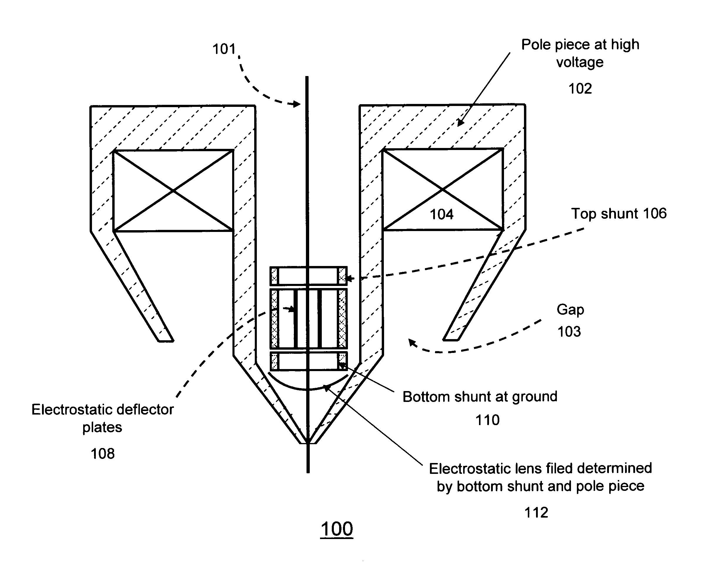
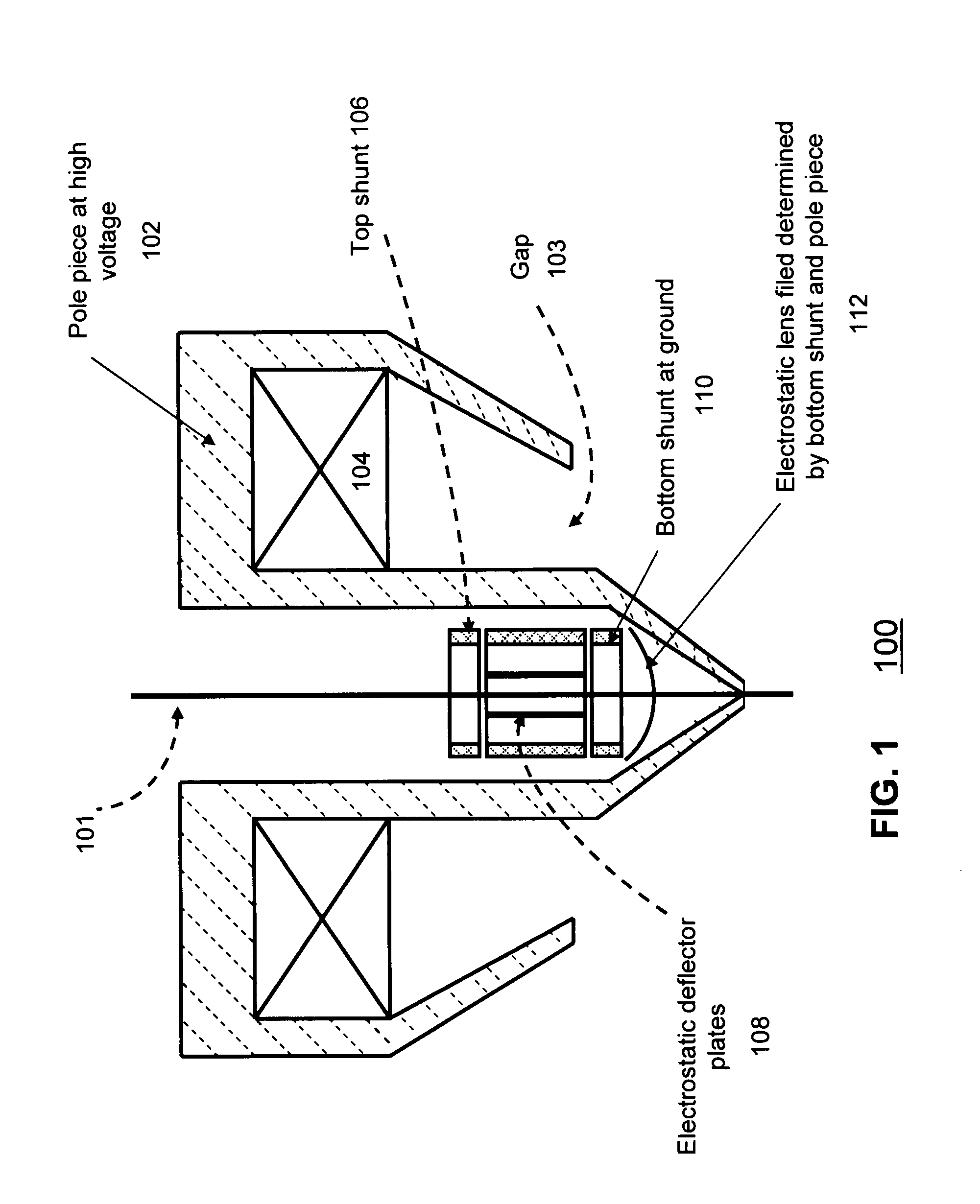
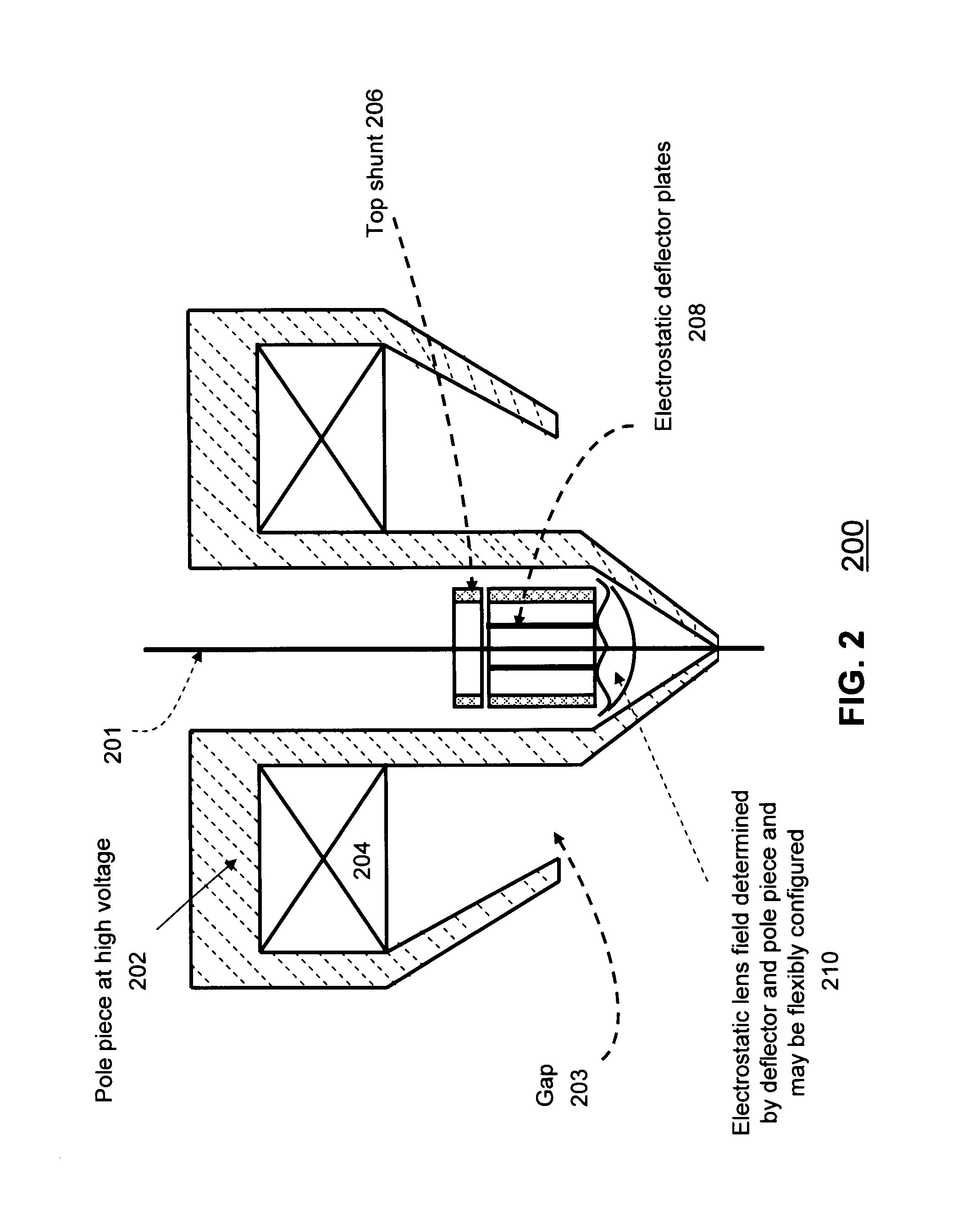
[0016]Immersion Objective Lenses

[0017]Low-voltage scanning electron microscopes (SEMs) often use immersion objective lenses because they tend to have superior resolution performance. Immersion objective lenses immerse the sample in a magnetic and / or decelerating electrostatic field. The highest resolution low voltage SEMs use both magnetic and electrostatic immersion. The magnetic immersion allows for very small working distances and small aberration coefficients. The use of electrostatic immersion to retard the primary electron beam just prior to the substrate further reduces the aberration coefficients and thereby further increases the resolution.

[0018]The landing energy of the primary electron beam is determined by the potential difference between the electron gun's cathode and the subsrate. The retarding field at the substrate is determined by the potential difference between the substrate and the objective lens pole piece above it.

[0019]To allow independent control of the landi...


PUM


Abstract

One embodiment relates to an objective lens utilizing magnetic and electrostatic fields which is configured to focus a primary electron beam onto a surface of a target substrate. The objective lens includes a magnetic pole piece and an electrostatic deflector configured within the pole piece. An electrostatic lens field is determined by the pole piece and the electrostatic deflector, and the electrostatic lens field is configured by adjusting offset voltages applied to plates of the electrostatic deflector. Other embodiments, aspects and features are also disclosed.

Description

CROSS-REFERENCE TO RELATED APPLICATION[0001]The present application claims the benefit of U.S. Provisional Patent Application No. 60 / 881,319, entitled “Objective Lens With Deflector Plates Immersed In Electrostatic Lens Field”, filed Jan. 19, 2007, by inventors Alexander J. Gubbens and Ye Yang, the disclosure of which is hereby incorporated by reference in its entirety.BACKGROUND OF THE INVENTION[0002]1. Field of the Invention[0003]The present invention relates to electron beam apparatus, including scanning electron microscopes and the like, and method of operating such apparatus.[0004]2. Description of the Background Art[0005]There is an increasing need for high-resolution scanning electron microscopes (SEMs) in all areas of development and manufacture of micro-electronic and opto-electronic components. High-resolution scanning electron microscopes are useful so as to visually evaluate sub-micrometer structures. High-resolution SEMs may be used to identify deviations from standard ...

Claims


Application Information

Patent Timeline
IPC IPC(8): G21K5/04
CPCH01J37/145H01J37/28H01J2237/1516G21K5/04H01J2237/1035
Inventor GUBBENS, ALEXANDER J.YANG, YE
Owner KLA TENCOR TECH CORP
Why Eureka
Try Eureka