Wind power system

wind power technology, applied in renewable energy generation, sustainable manufacturing/processing, greenhouse gas reduction, etc., can solve the problems of difficulty in building a wind power system beyond the megawatt scale at present, and achieve the effects of low production difficulty, low difficulty and cost in production, transportation, installation and maintenance, and relatively small volume of individual power generation units

Inactive Publication Date: 2014-04-15
NANJING YUNENG NEW ENERGY TECH
View PDF14 Cites 9 Cited by
  • Summary
  • Abstract
  • Description
  • Claims
  • Application Information

AI Technical Summary

Benefits of technology

[0004]One of objectives of the present invention is to provide a wind power generation system with vertical axis wind rotor, whose output power can be superposed and adjusted readily such that the output power of the system exceeds megawatt easily. Another objective of the present invention is to make it possible that the costs spent in production, transportation, installation and maintenance of the system are far below that of the conventional megawatt-class wind power generation system.
[0005]In order to achieve the above objectives, the present invention needs to solve one or more of the following main technical problems: first, how to combine a vertical axis wind rotor with one or several small size generator set(s) to construct an individual power generation system or power generation unit; second, how to efficiently array a plurality of power generation units in the space by a supporting tower so that the whole power generation system accomplishes megawatt-level power output; third, how to separately design a large scale vertical axis wind rotor from its axial and radial direction such that the large scale wind rotor is divided into several standard members to be machined and manufactured, thereby reducing the difficulties in production, transportation and installation of the large scale wind rotor.
[0006]In order to achieve the above objectives, the present invention follows a novel idea that “breaking up the whole into parts” and “assembling the parts into a whole” as the basic conception of the technical solution. That is to say, in the process of production and transportation of the wind rotor and generator set, each parts and components of the wind power system is miniaturized and modularized, i.e. “breaking up the whole into parts”. When all the parts reach a wind field, following the thought of “assembling the parts into a whole”, a wind power generation system suitable for the local wind field is built according to the design requests. By using the design of one huge wind rotor driving multiple generator sets and by arranging in the space an array of power generation units which are relatively easier to be manufactured, the total power output of the power generation units achieves megawatt scale, however building a wind power system beyond megawatts scale is still difficult at present. Meanwhile, the aggregate and adjustable power generation model of multiple power generation units can also lower the wind speed condition required to start the megawatt-class wind power generation system.

Problems solved by technology

By using the design of one huge wind rotor driving multiple generator sets and by arranging in the space an array of power generation units which are relatively easier to be manufactured, the total power output of the power generation units achieves megawatt scale, however building a wind power system beyond megawatts scale is still difficult at present.

Method used


Image

  • Wind power system
  • Wind power system
  • Wind power system

Examples


embodiment 1

[0071

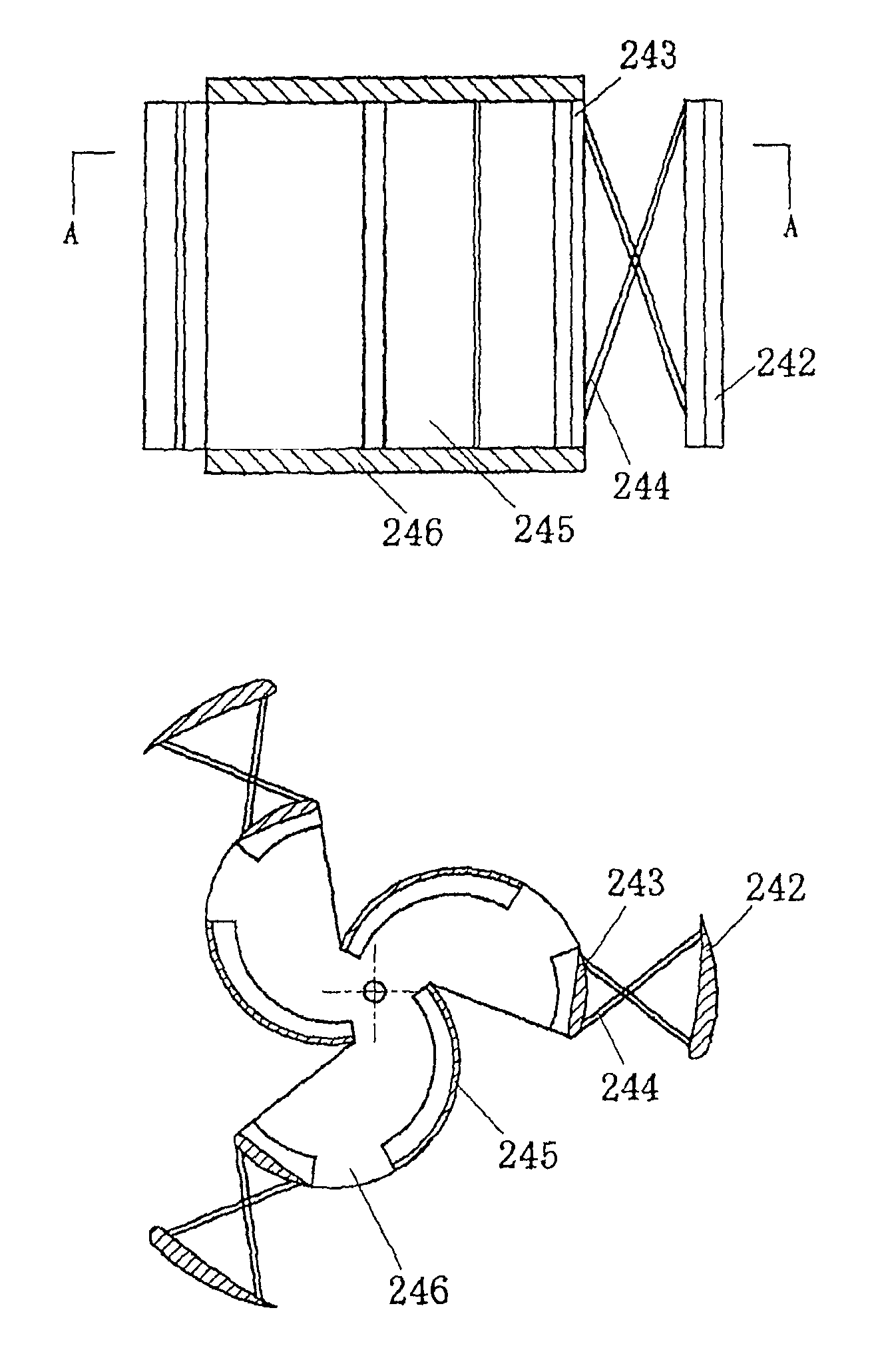
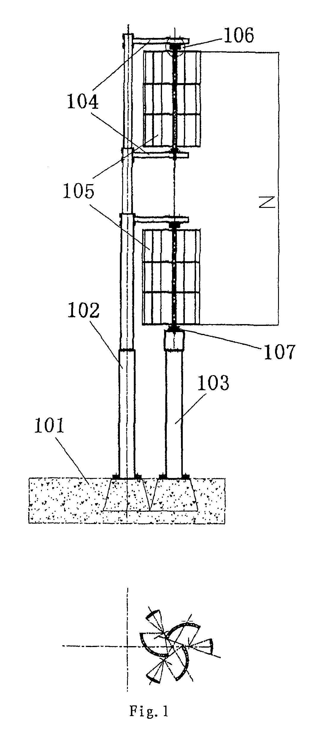
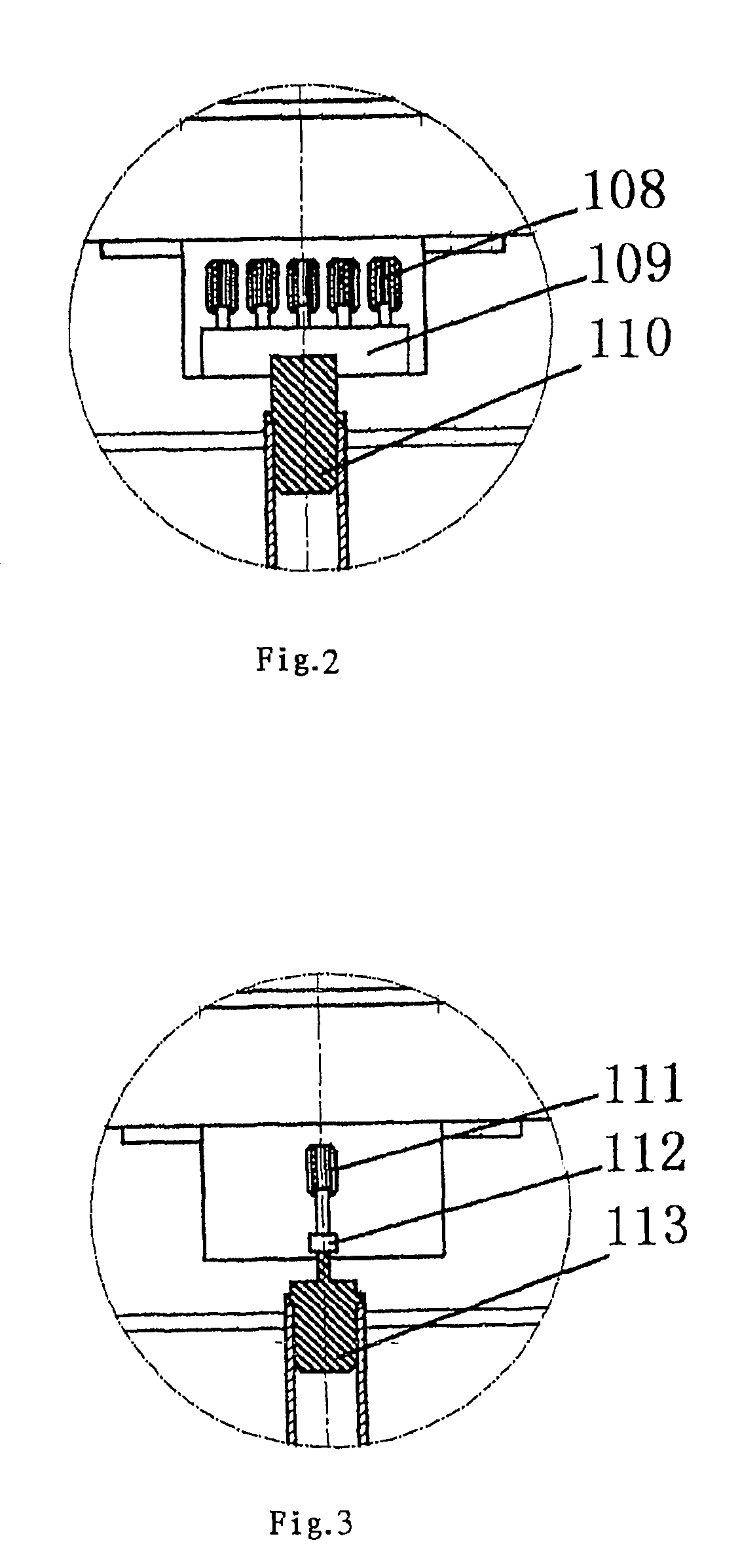
[0072]This embodiment represents a wind power generation system formed by single-column generator unit lying on one side. In particular, one of its preferred array structures is shown in FIG. 1. The tower 102 and the mast 103 are both securely fastened to the ground through a ground base 101. The beam 104 is positioned at different heights of the tower 102. The wind rotor 105 may be a combination of drag type blade and lift type blade. Individual wind rotor is located between adjacent upper and lower beams. While the lower end of the rotation shaft of the wind rotor is coupled with the locating bearing 107 arranged on the lower beam. As shown in FIG. 2, the upper end of each rotation shaft 110 of the wind rotor can be connected with five 10 KW generator sets via a drive gear box 109. The number of the generator units can be increased according to the requirement of the wind field design. All the electricity produced by every power generation unit is transmitted together to powe...

embodiment 2

[0073

[0074]Embodiment 2 represents a wind power generation system formed by two columns of power generation units lying on both side. In particular, one of its preferred array structures is shown in FIG. 4. The connection manner and operation procedure of the wind rotor and the generator set are same as that of Embodiment 1.

embodiment 3

[0075

[0076]Embodiment 3 represents a wind power generation system formed by three columns of power generation units with one column on the top and two columns on the bottom when viewed from the top view. In particular, one of its preferred array forms is shown in FIG. 5. The connection method and operation procedure of the wind rotor and the generator set are same as that of Embodiment 1.


PUM


Abstract

A wind power generation system is presented that includes a number of wind power generation units on the supporting tower, each wind power generation unit is formed by one vertical axis wind rotor and one or more power generation unit(s). The rotation shaft of the wind rotor is coupled with the rotor shaft of the single generator set through a connector, or the rotation shaft of the wind rotor is connected with the rotor shafts of multiple generator sets through a transmission mechanism. A helical vertical axis wind rotor and a lineal vertical axis wind rotor constructed by a drag type blade and a lift type blade is incorporated having a disassembling and splicing design. With this configuration, the number of the generator sets connected to the single wind rotor in the power generation unit may be adjusted in real time in accordance to different conditions.

Description

CROSS-REFERENCE TO RELATED APPLICATIONS[0001]This application is National Stage of PCT / CN2009 / 000229 filed Mar. 4, 2009, which claims priority to Chinese application No. 200810020389.0 filed Mar. 4, 2008 and Chinese application No. 200910028373.9 filed Jan. 22, 2009, the entire contents of each which are incorporated herein by reference.TECHNICAL FIELD[0002]The present invention relates to a wind power generation equipment, especially a super large scale wind power generation equipment.BACKGROUND TECHNIQUES[0003]If the large scale wind power generation equipment, in particular the megawatt-class wind power generation equipment, adopts the conventional horizontal axis type paddle blades, one single blade will have a length up to fifty to seventy meters. The production, transportation and installation of the paddle blade and the generator set as well as the tower erection or the like will meet problems. In the recent years, it is well accepted in the wind power industry that the large...

Claims


Application Information

Patent Timeline
Patent Type & Authority Patents(United States)
IPC IPC(8): F03D3/06
CPCF03D3/061F03D3/02F16C39/063Y02B10/30F05B2240/213F03D3/062F05B2240/302Y02E10/74F05B2240/212F16C2300/14F05B2250/15F05B2240/51F05B2250/25F03D15/10F03D80/70F16C2360/31Y02P70/50
Inventor HU, GUOXIANG
Owner NANJING YUNENG NEW ENERGY TECH
Why Eureka
Try Eureka