Implantable one-piece heart prosthesis

a one-piece, heart technology, applied in the field of implantable one-piece heart prosthesis, can solve the problems of not necessarily equal diastole and systole duration

Active Publication Date: 2014-04-22
CARMAT CO LTD
View PDF4 Cites 0 Cited by
  • Summary
  • Abstract
  • Description
  • Claims
  • Application Information

AI Technical Summary

Benefits of technology

[0024]For the convenience of accommodating the prosthesis inside the pericardial cavity, it is also advantageous that said main actuator and said auxiliary actuator are provided in the vicinity of each other. In this case, in order to benefit from the anatomy, said main and auxiliary actua...

Problems solved by technology

However, with said correction flow rates generated by said auxiliary ...

Method used


Image

  • Implantable one-piece heart prosthesis
  • Implantable one-piece heart prosthesis
  • Implantable one-piece heart prosthesis

Examples


Embodiment Construction

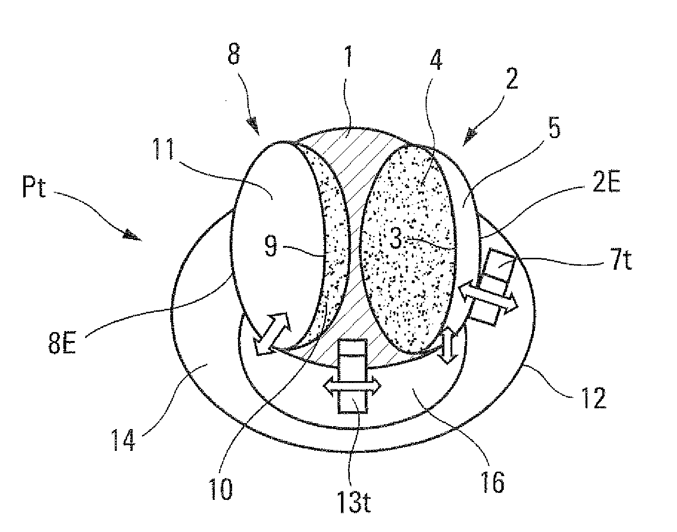
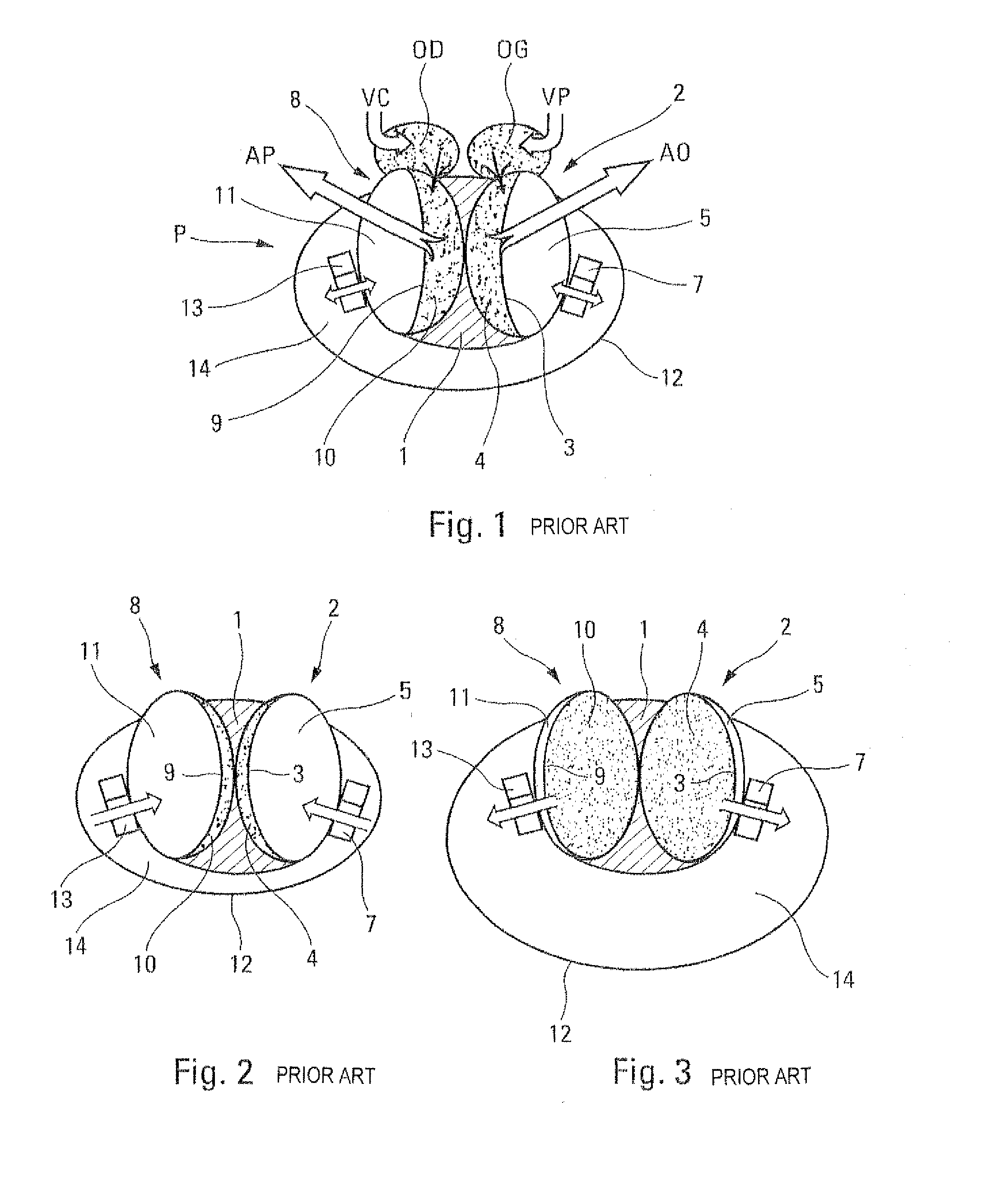
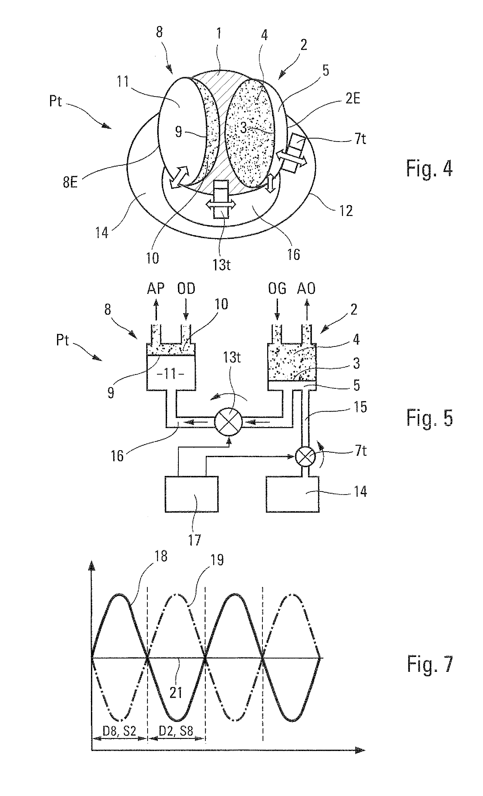
[0037]The known prosthesis P, schematically depicted in FIG. 1, is intended to replace the natural left and right ventricles of an ill heart (not shown), after ablation thereof. The prosthesis P should be able to be accommodated at least substantially in the portion of the pericardial cavity left free following removal of said natural ventricles.

[0038]As schematically depicted in FIG. 1, the prosthesis P comprises:[0039]a stiff body 1 in which an artificial left ventricle 2 is arranged, comprising a soft membrane 3 which sealingly partitions said artificial ventricle 2 into a chamber 4 for the blood flow and a chamber 5 for a hydraulic fluid, said blood chamber 4 being intended to be connected, on one side to the natural left atrium LA in communication with the pulmonary veins PV and, on the other side, to the aorta AO;[0040]a hydraulic actuator 7, for example of the volumetric motor pump type, in communication with the hydraulic fluid chamber 5 of the artificial left ventricle 2;[0...


PUM


Abstract

Disclosed is an implantable one-piece heart prosthesis having a driving artificial ventricle and a driven artificial ventricle. A main actuator is configured to transmit to the driving artificial ventricle diastolic and systolic flow rates having desired respective values for the driving artificial ventricle. An auxiliary actuator is configured to transmit to the driven artificial ventricle correction systolic and diastolic flow rates that correct the systolic and diastolic flow rates transmitted by the main actuator to the driven artificial ventricle.

Description

FIELD OF THE INVENTION[0001]This invention relates to an implantable one-piece heart prosthesis.BACKGROUND OF THE INVENTION[0002]From document U.S. Pat. No. 5,135,539, a heart prosthesis being implantable in the pericardial cavity of a patient is known, said prosthesis being capable of replacing the natural left and right ventricles of said patient after ablation thereof and comprising:[0003]a stiff body in which artificial left and right ventricles are arranged, each of these artificial ventricles comprising a soft pulsatile membrane:[0004]which is capable of beating under the action of a hydraulic fluid, and[0005]which is provided within a cavity sealingly partitioned by said membrane into two chambers, one of which is intended for blood flow and the other of which is intended for said hydraulic fluid, the blood chamber of the artificial left ventricle being intended to be connected to the natural left atrium and to the aorta, whereas the blood chamber of the artificial right vent...

Claims


Application Information

Patent Timeline
IPC IPC(8): A61M1/10
CPCA61M1/106A61M1/12A61M60/268A61M60/148A61M60/546A61M60/427A61M60/196A61M60/523A61F2/02
Inventor GRIMME, MARCGOURGUES, JEAN-ELIECARPENTIER, ALAINWARTELLE, CLAUDE
Owner CARMAT CO LTD
Why Eureka
Try Eureka