Device for generating a plasma discharge for patterning the surface of a substrate

a technology of plasma discharge and substrate, which is applied in the field of generating a plasma discharge for patterning the surface of a substrate, can solve the problems of complicated high voltage pulse control, high cost of mask, and use of thin substrates, etc., and achieves fast patterning of substrates, simple control, and long electrode life

Inactive Publication Date: 2014-04-22
VISION DYNAMICS HLDG
View PDF44 Cites 152 Cited by
  • Summary
  • Abstract
  • Description
  • Claims
  • Application Information

AI Technical Summary

Benefits of technology

[0007]It is an object of the invention to provide a device for generating a plasma discharge, suitable for maskless direct patterning of a substrate. The device should preferably have simple control, long electrode life, be able to quickly pattern the substrate and / or be suitable for a large range of substrates, e.g. thick and thin substrates.
[0010]This provides the advantage that the plasma can be switched on or off by placing the first electrode in the first or second position respectively using the positioning means. Hence, no control of the high voltage supply to the electrodes is necessary.
[0012]In another embodiment, the positioning means are further arranged for positioning the second electrode in synchronism with the first electrode. This provides the advantage that the first and second electrode together, e.g. as a writing head, can be scanned along the surface of the substrate, hence scanning the plasma along the surface. Moreover, the first and second electrode being scanned in synchronism, e.g. side-by-side, provides the advantage that no electrode is required behind the substrate, so that also non-sheet-shaped substrates, such as thick substrates, irregularly shaped substrates and / or three-dimensional substrates can be scanned.
[0014]Preferably, the device further comprising a housing, wherein the first electrode is at least partially surrounded by the housing, and the first electrode is movable with respect to the housing. The housing may be electrically insulating. Thus, the first electrode may be protected by the housing. It is for instance possible that the first electrode is substantially fully retracted within the housing when in the second position and partly protrudes from the housing when in the first position. Thus, the first electrode may be protected from dirt, debris or reaction products of the plasma.
[0020]According to a second aspect of the invention, the positioning means are further arranged for positioning the second electrode in synchronism with the first electrode, wherein the positioning means are not necessarily arranged for positioning the first electrode with respect to the second electrode. This also provides the advantage that the first and second electrode together, e.g. as a writing head, can be scanned along the surface of the substrate, hence scanning the plasma along the surface. Moreover, the first and second electrode being scanned in synchronism, e.g. side-by-side, provides the advantage that no electrode is required behind the substrate, so that also thick substrates, irregularly shaped substrates and / or three-dimensional substrates can be scanned.

Problems solved by technology

This may be a good method for mass production, but, as making a mask is quite expensive and takes time, a maskless method would be preferable for production of smaller amounts.
Although not using a physical mask, this device has the disadvantage that complicated precise control of the high voltage pulses is required.
Further, since the device uses a counter electrode behind the substrate, only thin substrates may be used.
Also, spark discharge may not be desirable for certain processes of deposition, etching and hydrophilation.

Method used


Image

  • Device for generating a plasma discharge for patterning the surface of a substrate
  • Device for generating a plasma discharge for patterning the surface of a substrate
  • Device for generating a plasma discharge for patterning the surface of a substrate

Examples


first embodiment

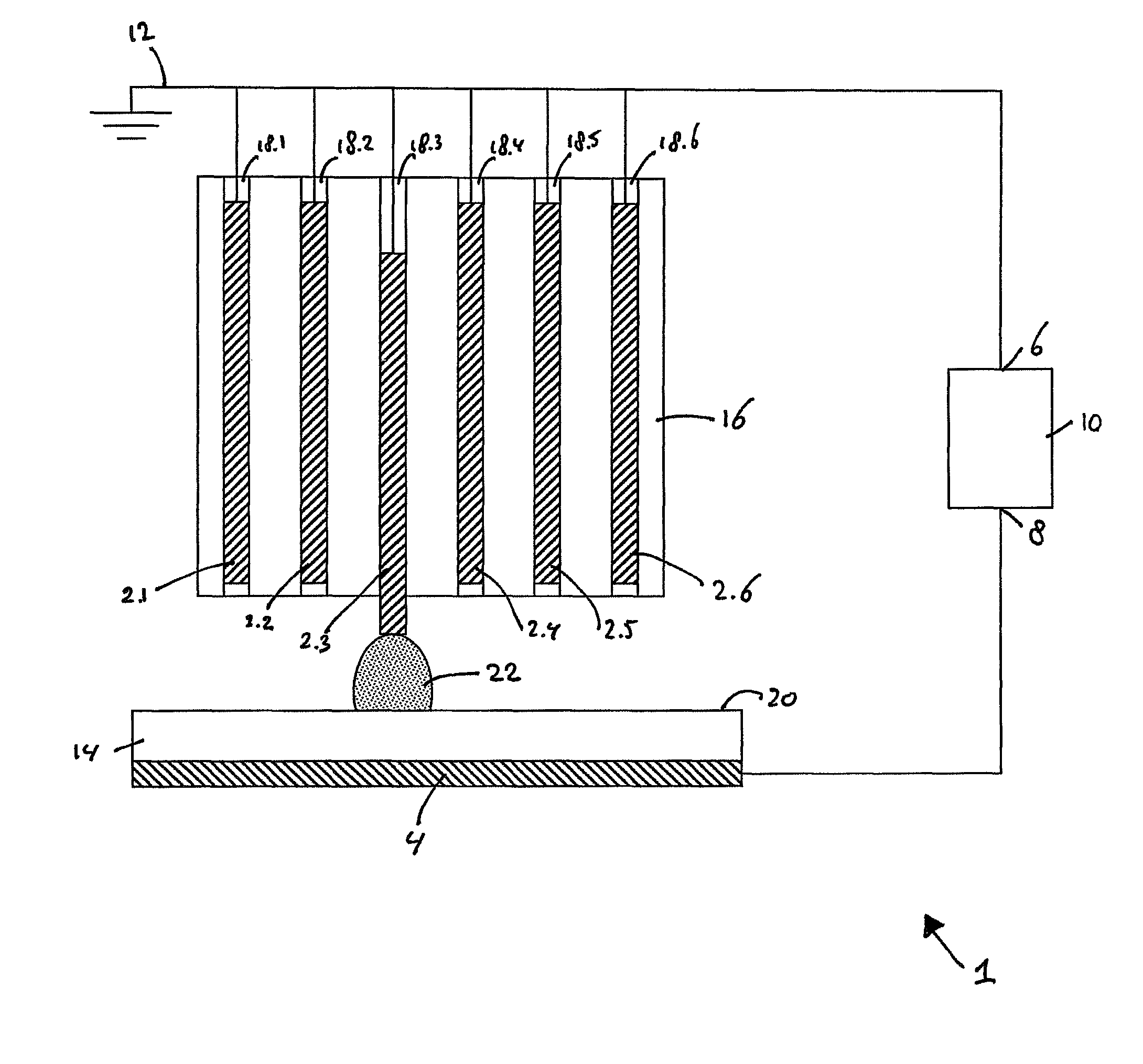
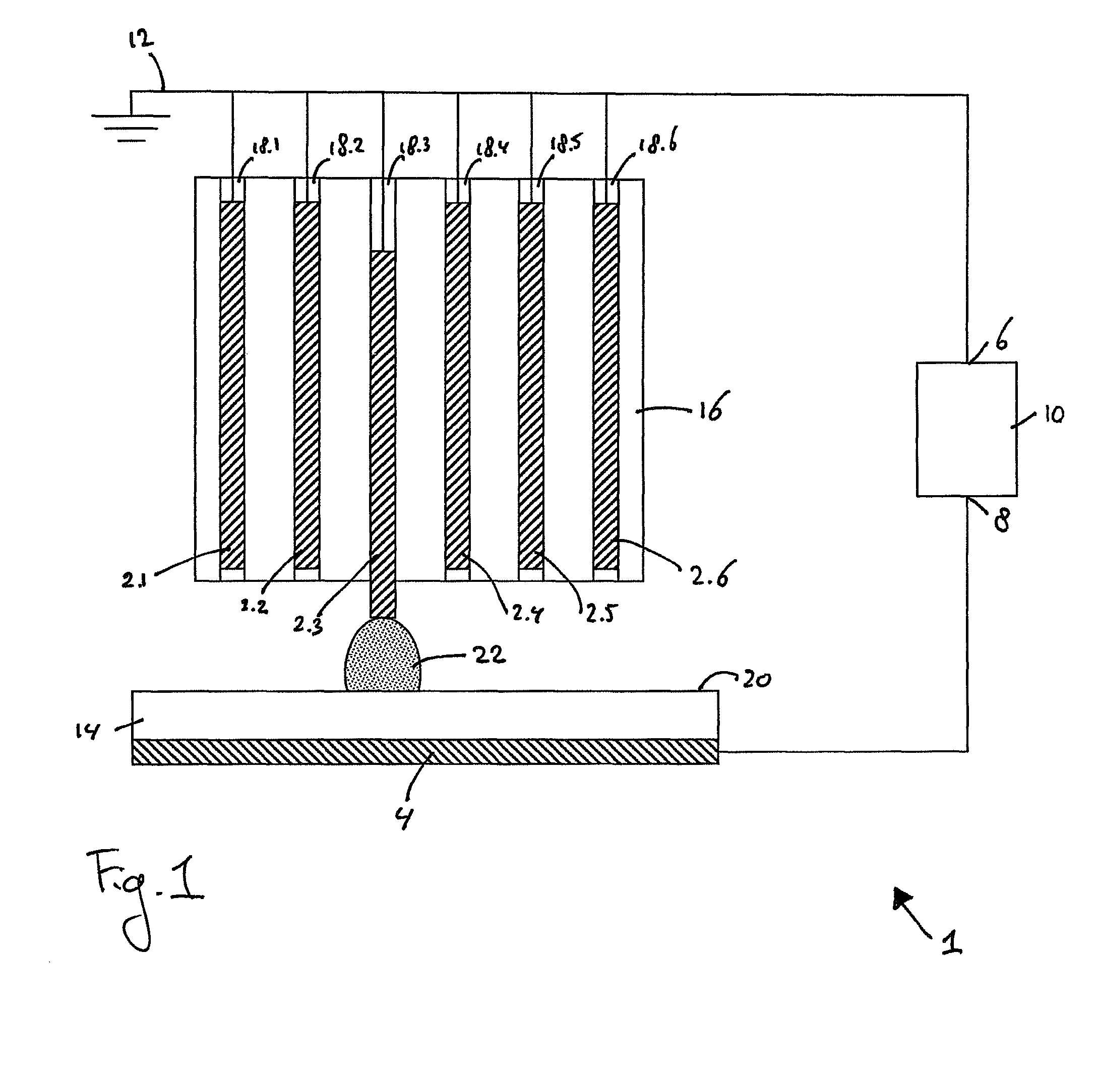
[0034]FIG. 1 shows a schematic representation of a device 1 for generating a plasma discharge for patterning the surface of a substrate according to the invention.

[0035]In this example, the device 1 comprises a plurality of first electrodes 2.i (i=1, 2, 3, . . . ). In this example, the first electrodes 2.i are designed as elongate pens. The device 1 further comprises a second electrode 4. In this example, the second electrode is plate-shaped. The first and second electrodes 2.i, 4 are electrically conducting connected to terminals 6,8 of a high voltage source 10 respectively. The high voltage source 10 is arranged for generating a high voltage difference between the first electrodes 2.i and the second electrode 4. In this example, the first electrodes 2.i are also connected to ground at 12. It will be appreciated that the first electrodes may be negatively charged with respect to the second electrode or vice versa, e.g. depending on whether ions or electrons are desired to impact on...

second embodiment

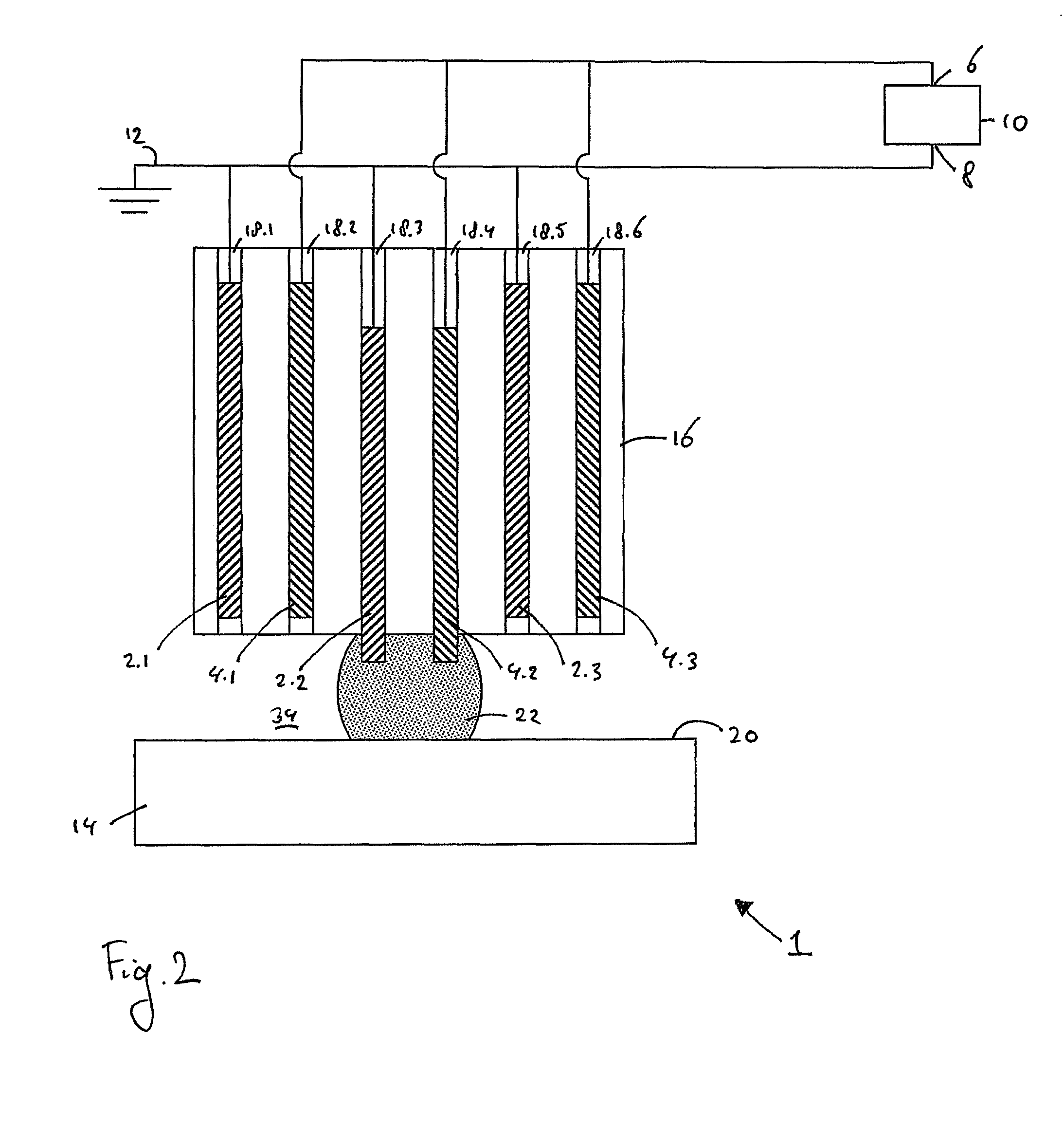
[0047]FIG. 2 shows a schematic representation of a device 1 according to the invention. In this example, the plurality of first electrodes 2.i and a plurality of second electrodes 4.j (j=1, 2, 3, . . . ) are positioned side-by-side. In this example both the first and second electrodes are slidably housed in their respective bores 18.k (k=1, 2, 3, . . . ).

[0048]The device 1 as shown in FIG. 2 may be operated in the following manner.

[0049]The substrate 14 is placed near the first and second electrodes, 2.i, 4.j. The high voltage difference is set and maintained between the first and second electrodes.

[0050]When the surface 20 of the substrate 14 is to be selectively treated with a plasma, the location where the surface 20 is to be treated is determined. The first electrode 2.i and the second electrode 4.j closest to the determined location on the surface are selected. In this example, first electrode 2.2 and second electrode 4.2 are selected.

[0051]Initially all first electrodes 2.i an...

sixth embodiment

[0079]FIG. 6 shows a device 1 according to the invention. In this embodiment a conventional inkjet print head 35 is converted for the purpose of providing the plasma discharge. In this example, the inkjet print head comprises a plurality of nozzles 37.n (n=1, 2, 3, . . . ). Per nozzle, two piezo-electric elements 36,38 are positioned adjacent an internal ink chamber 40. According to the modification, the piezo-electric elements 36,38 are electrically conducting connected to the terminals 6,8 of the high voltage source 10, respectively. When a high voltage difference is maintained between the piezo-electric elements 36,38, these act as the first and second electrodes 2.i, 4.j.

[0080]The device of FIG. 6 may be operated as follows. Instead of an ink, a gas flow is fed into the print head 35, as indicated with arrow G. When the surface 20 of the substrate 14 is to be selectively treated with a plasma, the location where the surface 20 is to be treated is determined. The nozzle 37.n and...


PUM

PropertyMeasurementUnit
voltageaaaaaaaaaa
electrical conductingaaaaaaaaaa
three dimensional structureaaaaaaaaaa

Abstract

Device for generating a plasma discharge for patterning the surface of a substrate, comprising a first electrode having a first discharge portion and a second electrode having a second discharge portion, a high voltage source for generating a high voltage difference between the first and the second electrode, and positioning means for positioning the first electrode with respect to the substrate, wherein the positioning means are arranged for selectively positioning the first electrode with respect to the second electrode in a first position in which a distance between the first discharge portion and the second discharge portion is sufficiently small to support the plasma discharge at the high voltage difference, and in a second position in which the distance between the first discharge portion and the second discharge portion is sufficiently large to prevent plasma discharge at the high voltage difference.

Description

[0001]This application is U.S. National Phase of International Application No. PCT / NL2008 / 050555, filed Aug. 20, 2008, designating the United States, and published as WO 2010 / 021539 on Feb. 25, 2010.[0002]The invention relates to a device for generating a plasma discharge for patterning the surface of a substrate, especially to such device comprising a first electrode having a first discharge portion and a second electrode having a second discharge portion, a high voltage source for generating a high voltage difference between the first and the second electrode, and positioning means for positioning the first electrode with respect to the substrate.BACKGROUND OF THE INVENTION[0003]It is well-known that plasma's can be used to treat a surface; with the use of a plasma, it is possible to etch, to deposit a material onto a substrate, and / or to change a property of a surface of a substrate, e.g. changing it from hydrophobic to hydrophilic and chemical attachment of atoms. The latter can...

Claims


Application Information

Patent Timeline
Patent Type & Authority Patents(United States)
IPC IPC(8): C23F1/00
CPCH05H1/24H05H2001/2481H05H2001/466B41C1/1066H05H2240/10H05H1/2475H05H1/2481H05H1/466
Inventor BLOM, PAULUS PETRUS MARIAROSING, PHILIPSTEVENS, ALQUIN ALPHONS ELISABETHHUIJBREGTS, LAURENTIA JOHANNABOS, EDDY
Owner VISION DYNAMICS HLDG
Why Eureka
Try Eureka