
Source-channel combined coding method and satellite broadcasting system using the same

a combined coding and satellite broadcasting technology, applied in the direction of transmission monitoring, coding, instruments, etc., can solve the problems of reduced satellite broadcasting availability, reduced satellite broadcasting quality, and severe attenuation, so as to achieve the effect of solving

Inactive Publication Date: 2014-04-22
ELECTRONICS & TELECOMM RES INST
View PDF14 Cites 3 Cited by
  • Summary
  • Abstract
  • Description
  • Claims
  • Application Information

AI Technical Summary

Benefits of technology

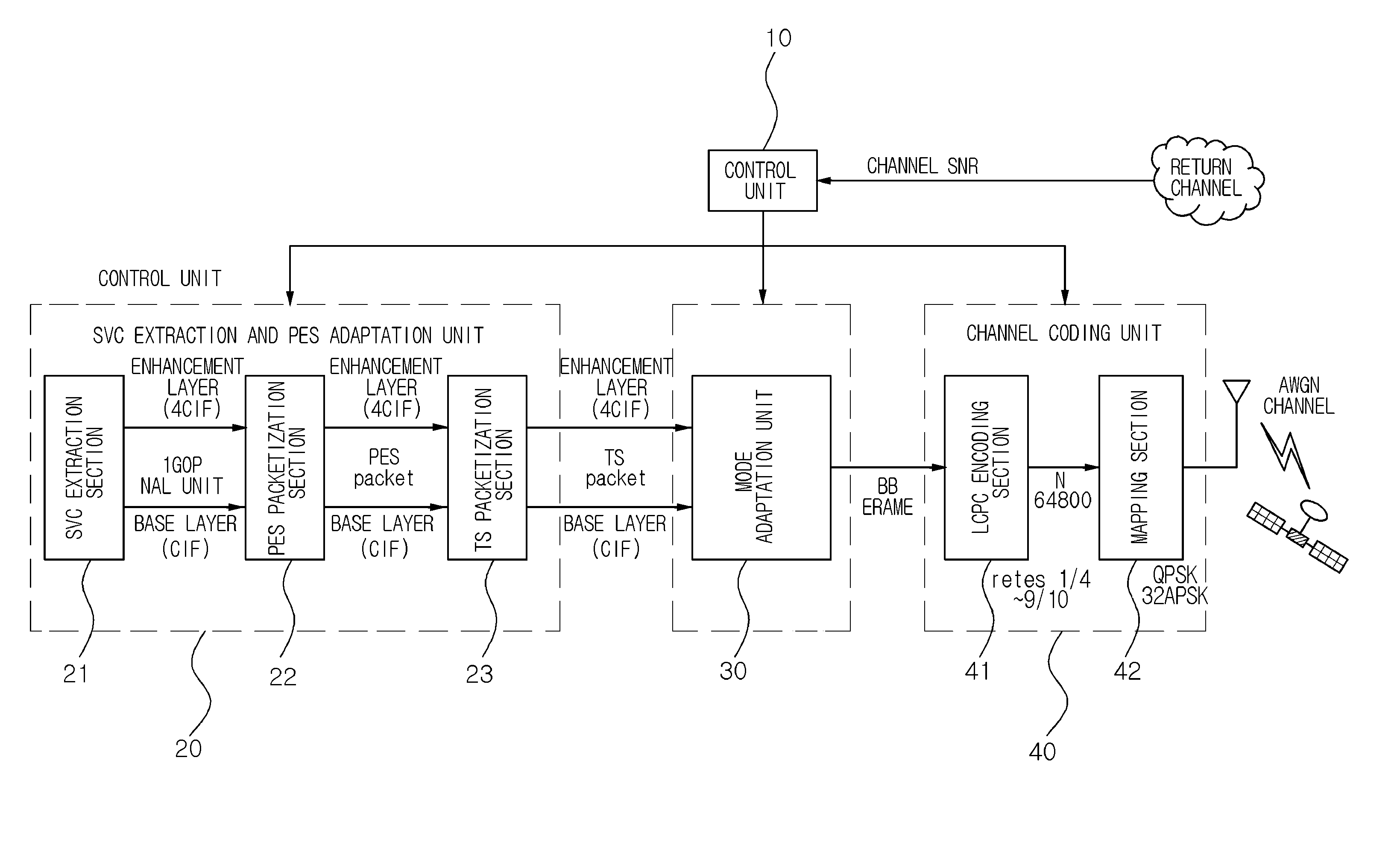
The present invention describes a method to effectively solve the problem of rain attenuation in a satellite broadcasting system by combining LDPC channel coding and SVC source coding. This method does not require any change in the structure of the system. The technical effects of this invention include improved reliability and stability of the satellite broadcasting system, as well as reduced loss of signal quality caused by rain attenuation.

Problems solved by technology

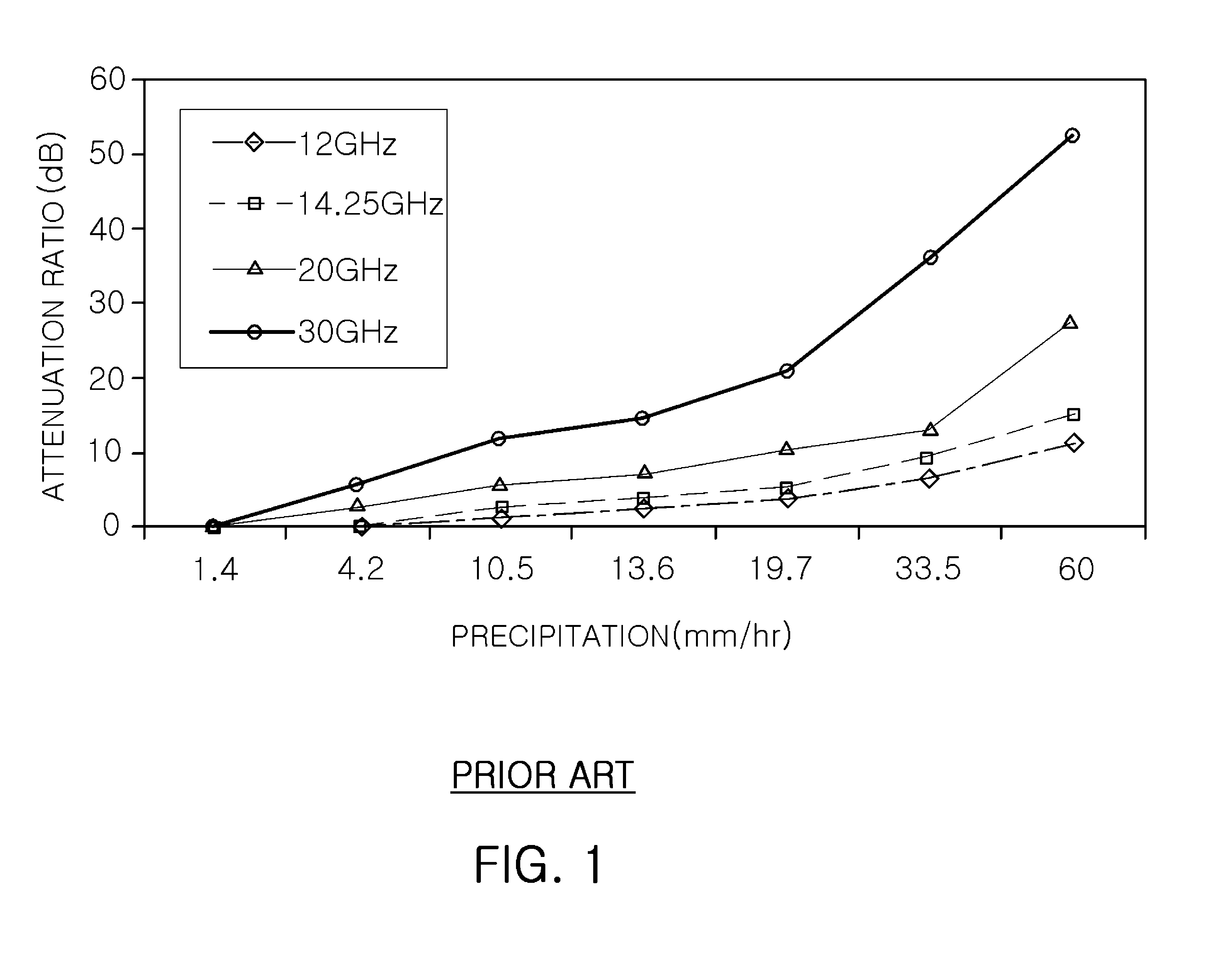
Therefore, the availability of satellite broadcasting may be reduced during bad weather conditions.
Therefore, the quality reduction of satellite broadcasting services caused by rain attenuation is very severe during this time.
Since the above-described transmitted power and beam control methods must be considered when a satellite is designed and manufactured, to be implemented, these methods require a new satellite which satisfies the requirements, and an additional cost for realizing the technology inevitably increases.
The SVC scheme, which is an extended coding scheme of H.264, has been developed to solve problems such as the fact that scalability based on the SVC scheme attempted by the existing MPEG-2 and MPEG-4 schemes has low compression efficiency, composite scalability cannot be supported, and there are difficulties in implementing the scheme.

Method used


Image

  • Source-channel combined coding method and satellite broadcasting system using the same
  • Source-channel combined coding method and satellite broadcasting system using the same
  • Source-channel combined coding method and satellite broadcasting system using the same

Examples


Embodiment Construction

[0023]Exemplary embodiments of the present invention will now be described in detail with reference to the accompanying drawings. The invention may, however, be embodied in many different forms and should not be construed as being limited to the embodiments set forth herein. Rather, these embodiments are provided so that this disclosure will be thorough and complete, and will fully convey the scope of the invention to those skilled in the art. In the drawings, the thicknesses of layers and regions are exaggerated for clarity. Like reference numerals in the drawings denote like elements, and thus their description will be omitted.

[0024]When it is described that one component is ‘connected’ to another component, the one component may be directly connected to another component. However, it will be understood that yet another component may exist therebetween. On the other hand, when it is described that one component is ‘directly connected’ to another component, it will be understood th...


PUM


Abstract

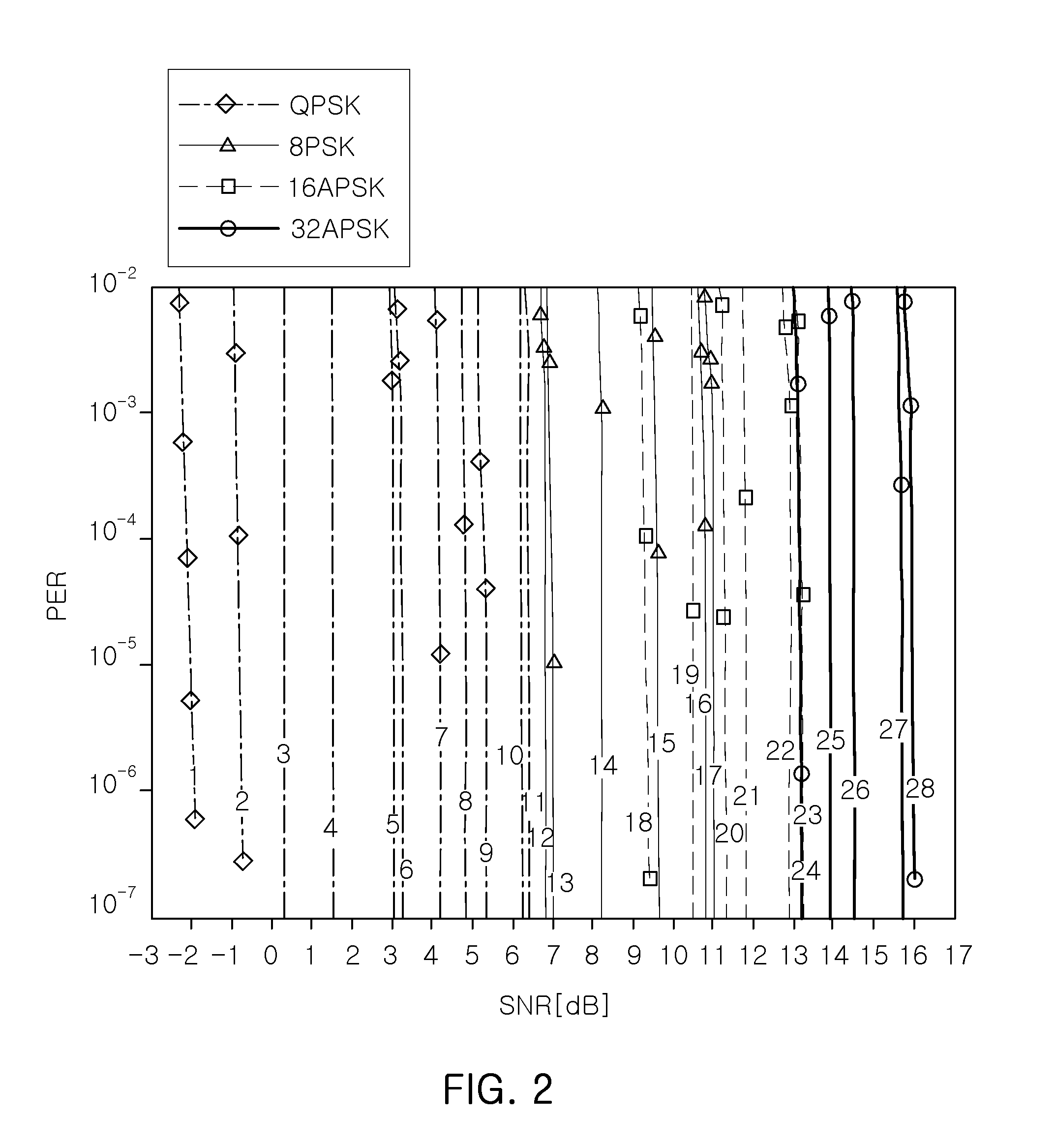
A source-channel combined coding method including: determining whether a channel signal-to-noise ratio (SNR) is varied or not; when it is determined that the channel SNR is varied, selecting a MODCOD suitable for the channel SNR by referring to a first table defining an SNR threshold value at which data transmission is performed without an error, for each MODCOD designating a low density parity check (LDPC) code rate and a modulation scheme; calculating a source coding rate by using an effective information bit rate of the selected MODCOD; extracting network abstraction layer (NAL) units for each layer from an inputted video frame so as to satisfy the calculated source coding rate, and packetizing the extracted NAL units; binding packets to configure a baseband (BB) frame; and LDPC coding and modulating the BB frame through the code rate and the modulation scheme which are designated by the selected MODCOD.

Description

CROSS-REFERENCE TO RELATED APPLICATIONS[0001]This application claims the priority of Korean Patent Application No. 10-2009-0117918 filed on Dec. 1, 2009, in the Korean Intellectual Property Office, the disclosure of which is incorporated herein by reference.BACKGROUND OF THE INVENTION[0002]1. Field of the Invention[0003]The present invention relates to a source-channel combined coding method, which applies scalable video coding (SVC) video to a digital video broadcasting-satellite 2 (DVD-S2) broadcasting service to reduce rain attenuation while minimizing a structural change of a satellite broadcasting system and, and a satellite broadcasting system using the same.[0004]2. Description of the Related Art[0005]Recently, satellite broadcasting technology has been replaced with a high-performance digital transmission scheme which is able to realize a high sound quality and provides various additional services. Therefore, existing DVB-S systems are being developed into DVB-S2 systems cap...

Claims


Application Information

Patent Timeline
Patent Type & Authority Patents(United States)
IPC IPC(8): H03M13/00
CPCH04H20/51H04H20/74H04H40/90H04N7/20H04N7/015
Inventor LEE, IN KICHANG, DAE IGSEO, KWANG DEOKCHI, WON SUP
Owner ELECTRONICS & TELECOMM RES INST
Learn More