Bulk material handling vehicle

a technology for handling vehicles and bulk materials, applied in the field of vehicles, can solve problems such as stability problems, consequential limit on carrying capacity, and lack of vehicle stability, and achieve the effects of enhancing volume, rapid dumping of contents, and maintaining vehicle stability

Active Publication Date: 2014-04-29
MAXITRANS AUSTRALIA
View PDF9 Cites 0 Cited by
  • Summary
  • Abstract
  • Description
  • Claims
  • Application Information

AI Technical Summary

Benefits of technology

[0016]The upper container body may thus provides an extension “hood” additional load carrying capacity above the lower container body. In this way, high volume load carrying is achieved.
[0021]The upper and lower container bodies provide increased load carrying capacity whilst the unloading configuration and operation maintains stability of the vehicle whilst effectively and efficiently unloading material through the open side door and the increased unloading gap created by operatively opening the gap between the lower and upper bodies through the respective pivoting actions.
[0022]Preferably the lower body has a floor structure that is generally bowl shape in cross section, which assists in collecting liquid draining from or through the load. The arrangement assists collection of such liquid, which liquid can be toxic or at least hazardous to health, and allows the liquid to be readily drained off or at least reduces contact with the load.
[0024]One or more of the end walls of the upper or lower container body may include extension covers which cover over the extension walls and prevent material of the load from interfering with the extension walls during the opening and closing operations of the container. These extension covers may be formed of a flexible or semi flexible material, and may be removable / replaceable eg when worn or damaged. They may be retained in place by respective releasable retainer means, such as upper edge mounting strips provided at the upper edge of the upper container body.
[0031]The combined effect of raising and laterally displacing the body, from its normal transport position on the chassis, to the discharge position, and the movement of the base to an inclined discharge disposition as the body is raised, results in the ability to achieve a rapid and total discharge of the contents of the upper and lower bodies whilst maintaining stability of the vehicle. Because the upper container body is raised, and the side door opened with the lower body tipped, the contents of the body will be rapidly gravity discharged from the enhanced volume of the combined upper and lower bodies. Further the material can be discharged through the bottom of the body across the full cross-section of the body thereby achieving a very rapid dumping of the contents. Also the lateral displacement of the lower body results in the contents being deposited outwardly of the path of the vehicle wheels to not interfere with the passage of the vehicle wheels during entry and exit of the vehicle.
[0032]The upper container body may be connected to the lower container body through a mounting means, such as a mounting plate. An upper container body hinge bush and pin arrangement may be used to connect to the cylindrical (pipe) body combing. A seal lubrication means may be provided, which may be formed including or consisting of plastics material to aid in the lubrication of the pivot system and reduce likelihood of material from leaking out through the side as the hinged upper conveyor body is raised. The seal means may be mounted to the pivotable upper container body rotate around a pipe body combing to ensure a continued seal between the upper conveyor body and the pipe body combing.

Problems solved by technology

Another problem with the known constructions is the lack of stability of the vehicle during discharge, and the consequential limit on the carrying capacity thereof.
This can result in stability problems.
Also a problem arises from the fact that the dumped material is located close to the side of the vehicle and interferes with the passage of the vehicle into and out of the dump locations.
Such vehicles also have limited load carrying capacity restricted to the main load carrying body.
Restricted load carrying capacity results in more journeys being required to be made or additional vehicles, all both of which result in increased direct (fuel) or indirect (driver costs) haulage costs.

Method used


Image

  • Bulk material handling vehicle
  • Bulk material handling vehicle
  • Bulk material handling vehicle

Examples


Embodiment Construction

[0043]One or more embodiments of the present invention will hereinafter be described with reference to the accompanying drawings. These embodiments are not to be taken as limiting the generality of the present invention.

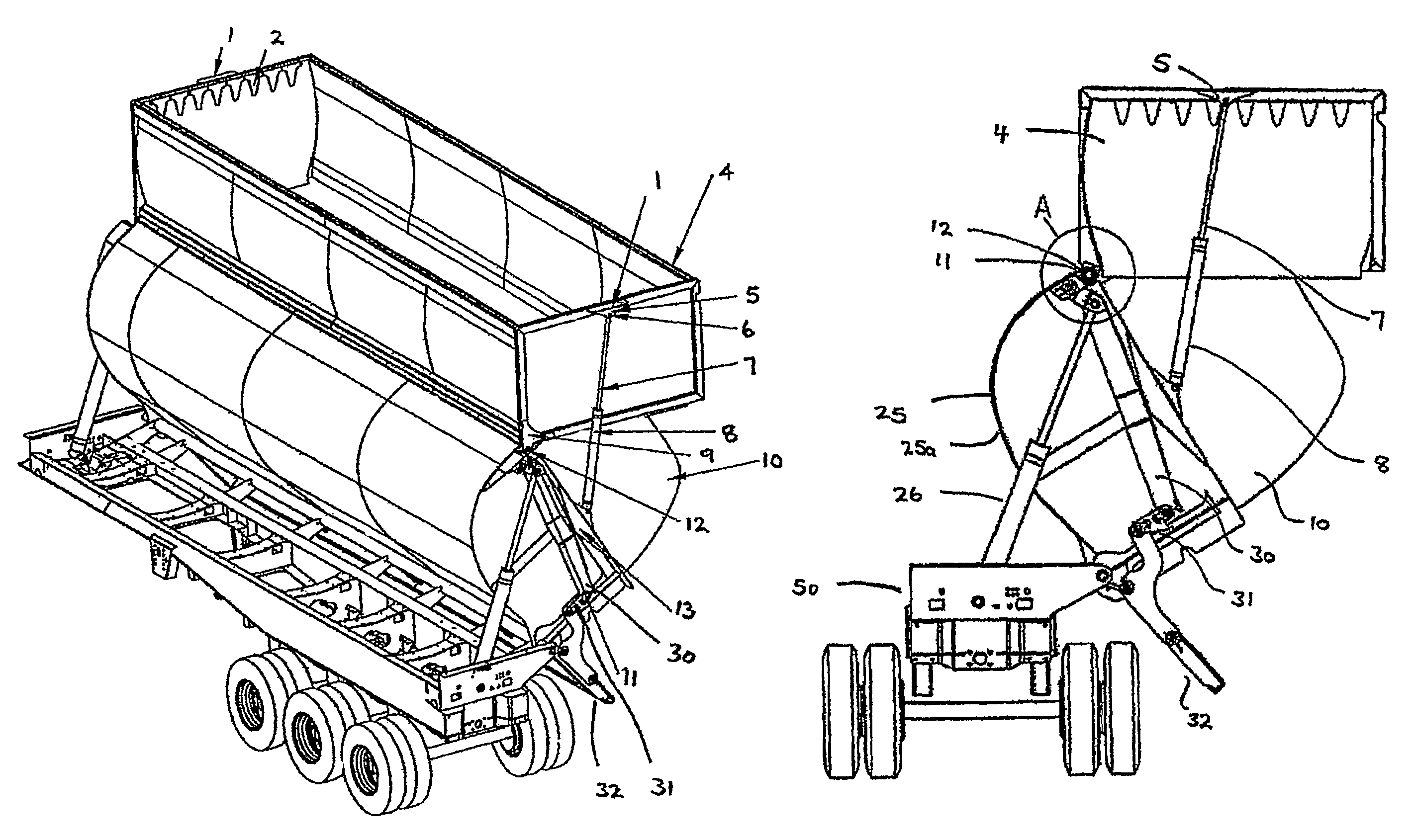
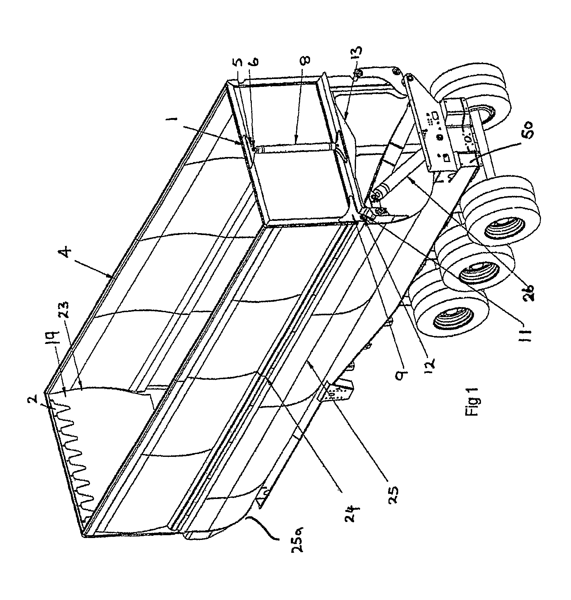
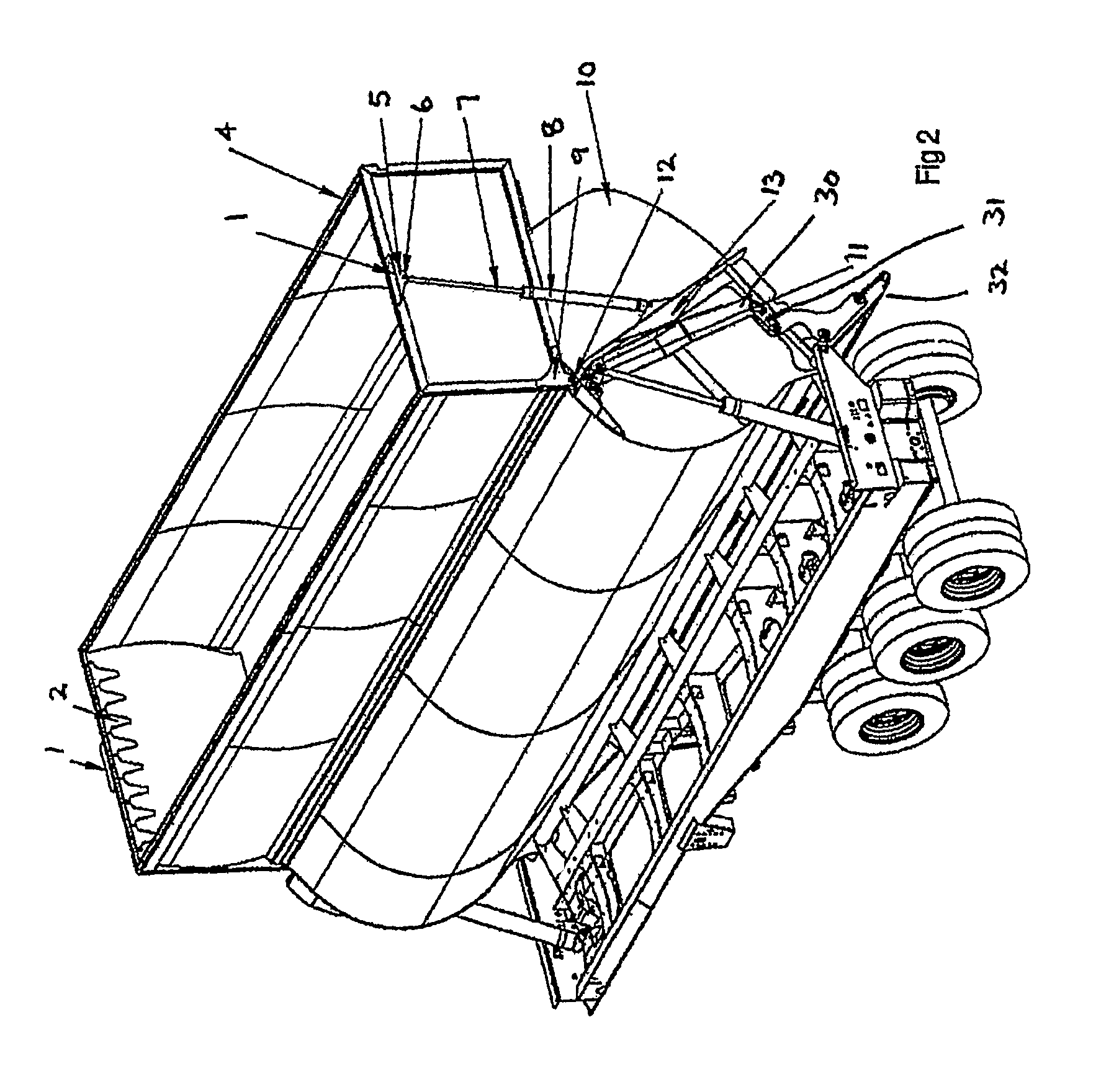
[0044]As can be seen in FIGS. 1 to 3, as the main lift hoist 26 extends to lift the lower container body 25, the upper container body hoist 8 extends simultaneously keeping the hinged body top extension 4 (upper container body) in a horizontal orientation as it lifts via a connection to the body 25 and the hinged body top extension 4 through top hoist mount 5 and bottom hoist mount 15.

[0045]The anti spill plate 10 is mounted to the body 25 to prevent product from leaking out the ends as the hinged body top extension 4 and the body 25 separate. The spill plate cover 19 prevents product from falling between the anti spill plate 10 and the hinged body top extension 4, the spill plate cover 19 can be made from a number of different materials such as metal, reinforced rub...


PUM


Abstract

A vehicle including a chassis (50) and a load carrying container supported thereon, the container arranged for pivotable movement relative to the chassis of the vehicle to discharge material from the container in a lateral direction to a side of the chassis, the container including a lower container body (25) and an upper container body (4) mounted thereto for operable movement with fespect to said lower container body to provide a selectively openable discharge passage e.g., via openable side discharge door (32), between the upper and lower container bodies when the upper and lower bodies pivot with respect to one another.

Description

TECHNICAL FIELD[0001]The present invention relates to vehicles for transporting and discharging bulk materials, such as for large volume refuse (waste) material, grain, ore or coal, wood chips, and other bulky light material.BACKGROUND[0002]A wide range of vehicle constructions have been proposed and used in relation to vehicles for transporting bulk materials, and there is generally a conception that one of the principal requirements of such a vehicle is the ability to be able to discharge the load in a safe and effective manner which will enable the vehicle to remain substantially stable during unloading.[0003]In known bulk material transport vehicles it is common to provide a material carrying body supported upon wheeled chassis for angular movement upon a fixed axis to an upwardly inclined discharge position. The axis about which the body tips is usually along one side of the chassis and hence a relatively high angle of tilt of the body is required to fully discharge the content...

Claims


Application Information

Patent Timeline
Patent Type & Authority Patents(United States)
IPC IPC(8): B60P1/00
CPCB60P1/165B60P1/28
Inventor OSTERMEYER, BERND
Owner MAXITRANS AUSTRALIA
Why Eureka
Try Eureka