Damper apparatus, damper tube assembly, and ink jet printer

a technology of damper tube and ink jet printer, which is applied in the direction of printing, other printing apparatus, etc., can solve the problems of varying damping function (pressure inhibiting function), affecting the quality of ink jet printing, and undischarged phenomenon of ink discharge, etc., to achieve the effect of reducing size and weight, and reducing the number of components

Inactive Publication Date: 2014-04-29
MIMAKI ENG
View PDF4 Cites 5 Cited by
  • Summary
  • Abstract
  • Description
  • Claims
  • Application Information

AI Technical Summary

Benefits of technology

[0013]According to the damper apparatus according to the first aspect of the invention, the damper apparatus which moves integrally with the carriage and the damper apparatus is provided at a midpoint of the ink flow channel which connects the ink tank and the printer head to cause the valve body of the damper apparatus to sense the acceleration and deceleration generated in association with the reciprocal motion of the carriage and, when the carriage is accelerated or decelerated, the valve body selectively displaced to a position closing the inlet port or the outlet port in accordance with the inertial law, so that the pressure variations in the printer head is inhibited, and the ink dripping phenomenon and the ink undischarged phenomenon may be prevented, and hence improvement of the printing quality is achieved. In contrast, when the carriage is not in acceleration and deceleration, the valve body is displaced to a position opening the inlet port and the outlet port by the action of the gravitational force to open the ink flow channel. Therefore, the ink from the ink tank can be supplied to the printer head through the ink flow channel without delay according to the discharge of ink.
[0014]In the damper apparatus having the configuration as described above, a bottom surface of the valve chamber includes an inclination or a curve having the deepest portion below the center position between the inlet port and the outlet port and extending downward to the deepest portion from the inlet port and the outlet port, and the valve body is formed of a rotating member which is capable of rolling on the bottom surface. Therefore, the valve body rolls along the bottom surface of the valve chamber in accordance with the inertial law and is selectively displaced to the position closing the inlet port or the outlet port according to the direction of the action of the inertial force to close the ink flow channel when the carriage is accelerated or decelerated. In contrast, when the carriage is not accelerated or decelerated, the valve body rolls downward on the bottom surface of the valve chamber by the action of the gravitational force, and displaced to the position opening the inlet port and the outlet port to open the ink flow channel. Therefore, since the ink flow channel can be opened and closed with the simple configuration that the valve body is caused to roll between the respective ports and the deepest portion by the action of the inertial force and the gravitational force to cause the valve body to positions closing and opening the respective ports, reduction of the number of components, reduction in size and weight, and cost reduction are achieved.
[0015]Also, the valve body is hung from the top surface of the valve chamber in the suspended state so as to be swingable with the supporting member, and is configured to perform the pendulum motion upon reception of the action of the inertial force and the gravitational force in association with the reciprocal motion of the carriage, and the inlet port and the outlet port are arranged on the swinging trajectory of the valve body of the pendulum motion, so that the valve body performs the pendulum motion in the valve chamber in accordance with the inertial law and is selectively displaced to a position closing the inlet port or the outlet port according to the direction of the action of the inertial force to close the ink flow channel when the carriage is accelerated or decelerated. In contrast, when the carriage is not accelerated or decelerated, the valve body remains standstill in the suspended state in the valve chamber by the action of a gravitational force, and opens the inlet port and the outlet port to open the ink flow channel. Therefore, since the ink flow channel can be opened and closed with a simple structure that the valve body is caused to perform the pendulum motion between the respective ports by the action of the inertial force and the gravitational force to be displaced between positions of closing and opening the respective ports, reduction of the number of component, reduction in size and weight, and cost reduction are achieved. In addition, since the valve body needs not to be rolled on the bottom surface, the abrasion caused by a contact between the valve body and the bottom surface does not occur on the valve body, so that occurrence of the seat-contact failure between the valve body and the seat surface formed in the periphery of the respective ports by the deformation of the valve body caused by abrasion with time is prevented.
[0016]The damper tube assembly according to the second aspect of the invention is the damper apparatus having the configuration described above, and at least one of the upstream side tube connected to the inlet port and capable of forming the ink flow channel on the side of the ink tank and the downstream side tube connected to the outlet port and capable of forming the ink flow channel on the side of the printer head. Therefore not only the same operational effects as described above are obtained, but also the assembly workability between the damper apparatus and the ink tube in the ink jet printer may be improved.
[0017]According to the ink jet printer in the third aspect of the invention, there is provided the ink jet printer including: the medium supporting portion configured to support the printing medium; the carriage having the printer head configured to discharge ink; the carriage moving mechanism configured to relatively move the carriage along the surface to be printed of the printing medium supported by the medium supporting portion; the ink tank configured to store ink; the ink tube configured to form the ink flow channel configured to connect the ink tank and the printer head; and the damper apparatus having the configuration described above. Therefore, for example, not only the same operational effects as described above is obtained, but also the more the velocity of acceleration and deceleration is increased, the larger inertial force acts, and hence the response of the valve body is improved and the respective ports are firmly closed. Therefore, further increase in velocity of the reciprocal motion of the carriage, that is, the increase in velocity of printing is also possible.

Problems solved by technology

In contrast, when the internal pressure of the printer head is significantly reduced, a meniscus formed in the nozzle is broken, and an air bubble is sucked into the printer head, which may cause an ink undischarged phenomenon that the discharge of ink is disabled (also referred to as “nozzle skip”) may occur.
However, the damper apparatus of this type has a problem in that the damping function (pressure inhibiting function) varies depending on an initial state of the damper chamber.
For example, even though the ink pressure acts on the pressurizing side when the damper film is deflected outward and the damper chamber is expanded to the maximum, the capacity in the damper chamber is not increased any longer, and hence the damping function does not work.
In contrast, even though the ink pressure acts on the depressurizing side when the damper film is deflected inward and the damper chamber is in the contracted state, the capacity of the damper chamber is not reduced any longer, and hence the damping function does not work as well in this case as well.
As described above, in the damper apparatus having the configuration of the related art, when the carriage is accelerated and decelerated in association with the reciprocal motion thereof, and the ink pressure variations occur in the pressurizing or depressurizing direction in the printer head correspondingly, the damping function may not work sufficiently.

Method used


Image

  • Damper apparatus, damper tube assembly, and ink jet printer
  • Damper apparatus, damper tube assembly, and ink jet printer
  • Damper apparatus, damper tube assembly, and ink jet printer

Examples


first embodiment

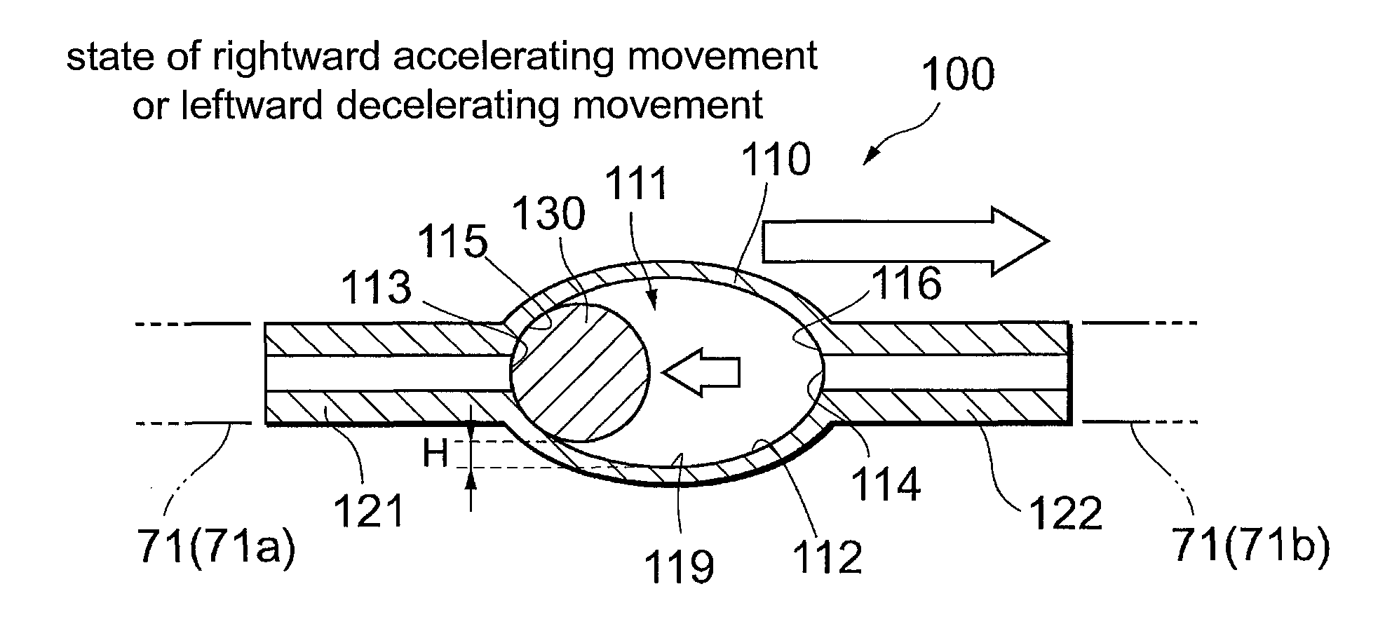
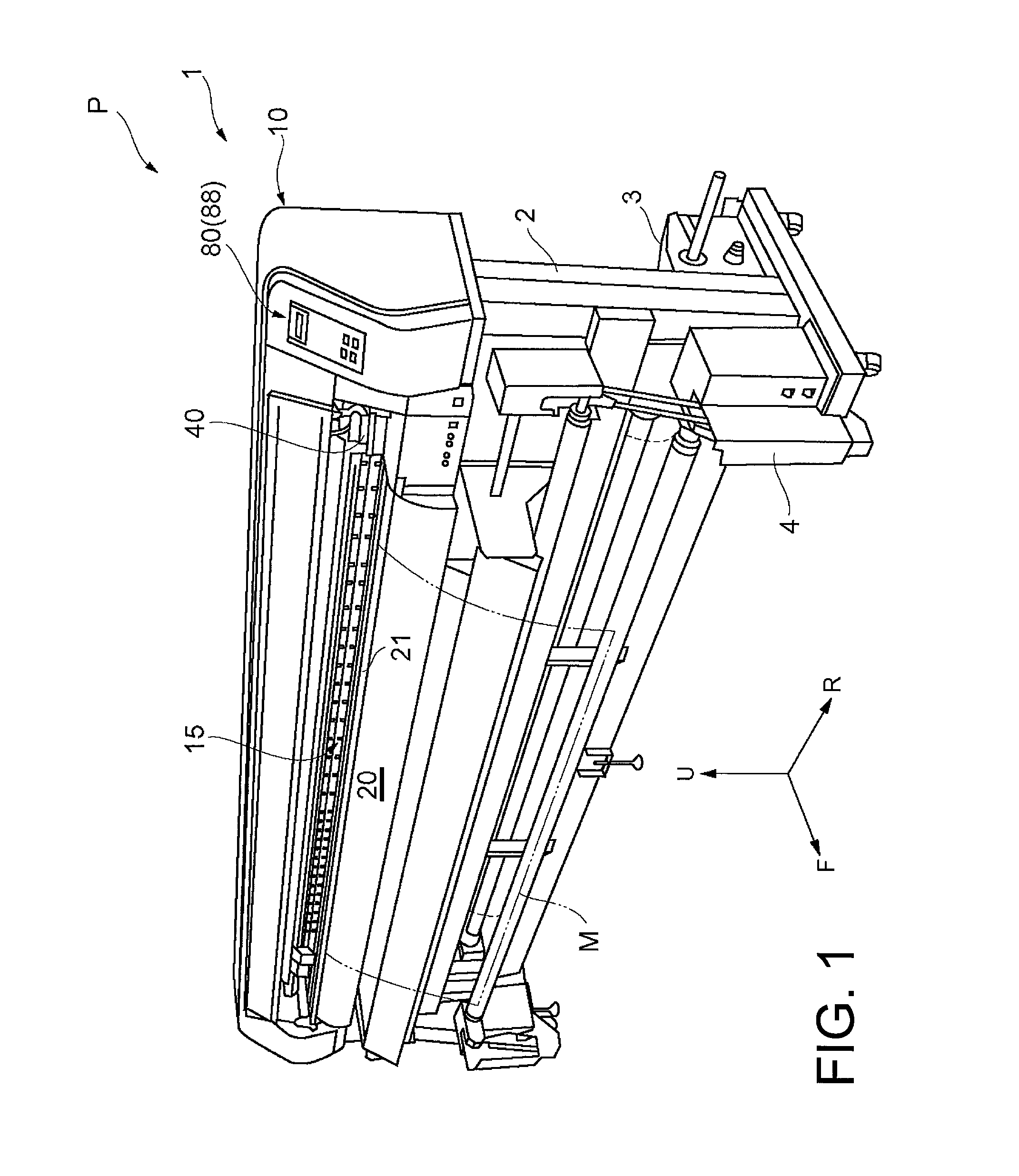
[0052]First of all, referring to FIG. 6 and FIGS. 7A to 7C, a damper apparatus 100 will be described. FIG. 6 illustrates a layout of the damper apparatus 100 in the printer apparatus P, and FIGS. 7A to 7C are cross-sectional side views of the damper apparatus 100. In FIG. 6, only one of the four damper apparatuses 100 is illustrated, and the carriage 40 is imaginarily illustrated using a double-dashed chain line.

[0053]The damper apparatus 100 includes a housing 110 provided at a midpoint of the ink tube 71 in a horizontal posture and a spherical valve body 130 stored in the housing 110, and is integrally held in the carriage 40 together with the printer head 60. In the following description, the left side of the damper apparatus 100 in FIGS. 7A to 7C is referred to as “upstream side” which communicates with the ink tank 70 and the right side is referred to as “downstream side” which communicates with the printer head 60 in the description.

[0054]The housing 110 is formed into a holl...

second embodiment

[0072]Referring now to FIG. 8, a damper apparatus 200 will be described. In the following description, the same components as those in the printer apparatus P described above are designated by the same reference numerals and the description will be omitted. FIG. 8 is a cross-sectional side view of the damper apparatus 200.

[0073]The damper apparatus 200 includes a substantially hollow cylindrical housing 210 provided in the ink tube 71 via left and right connecting tubes 221 and 222, and a spherical valve body 230 stored in the housing 210. In the damper apparatus 200 in the second embodiment, mainly a configuration of the housing 210 is different from the damper apparatus 100 in the first embodiment.

[0074]The housing 210 includes a valve chamber 211 which is partitioned by an inner peripheral wall of the housing 210, and serves as an ink flow channel. The valve chamber 211 has a conical surface 211b which defines a channel having a substantially circular cross section and is reduce...

third embodiment

[0078]Referring now to FIGS. 9A and 9B, a damper apparatus 300 will be described. In the following description, the same components as those in the printer apparatus P described above are designated by the same reference numerals and the description will be omitted. Here, FIG. 9A is a cross-sectional side view of the damper apparatus 300, and FIG. 9B is a cross-sectional view taken along the line indicated by arrows A-A in FIG. 9A.

[0079]The damper apparatus 300 includes a housing 310 provided in the ink tube 71 via left and right connecting tubes 321 and 322 extending obliquely upward, and a spherical valve body 330 stored in the housing 310. In the damper apparatus 300 in this embodiment, mainly a configuration of the housing 310 is different from the damper apparatus 100 in the first embodiment.

[0080]The housing 310 has a substantially rectangular tubular shape bent into an U-shape, and is formed with a valve chamber 311 which is partitioned by an inner peripheral wall of the hou...


PUM


Abstract

The invention provides a damper apparatus including a housing having a valve chamber and reciprocally moving integrally with a carriage, an inlet port communicating an ink flow channel on the upstream side and the valve chamber, an outlet port communicating the ink flow channel on the downstream side and the valve chamber, and a spherical valve body stored so as to be movable in the valve chamber, wherein the valve body moves relatively to a position for closing the inlet port or the outlet port upon reception of the inertial force in association with the acceleration and deceleration to close the ink flow channel when the carriage is accelerated or decelerated, and the valve body moves relatively to a position for opening the inlet port and the outlet port under its own weight to open the ink flow channel when the carriage is not accelerated and decelerated.

Description

CROSS-REFERENCE TO RELATED APPLICATIONS[0001]This application claims the priority benefit of Japan application serial no. 2011-124006, filed on Jun. 2, 2011. The entirety of the above-mentioned patent application is hereby incorporated by reference herein and made a part of this specification.BACKGROUND OF THE INVENTION[0002]1. Technical Field[0003]The present invention relates to a damper apparatus configured to open and close an ink channel connecting an ink tank and a printer head, a damper tube assembly, and an ink jet printer.[0004]2. Description of the Related Art[0005]An ink jet printer is an apparatus configured to draw information such as characters, graphics, patterns, images on a surface of an object to be printed by discharging ink droplets on a printing medium from nozzles of a printer head while moving the printer head formed generally with a number of nozzles reciprocally with respect to the printing medium. In the ink jet printer in this configuration, for example, a...

Claims


Application Information

Patent Timeline
Patent Type & Authority Patents(United States)
IPC IPC(8): B41J2/17
CPCB41J2/175B41J2/01B41J29/38
Inventor OHNISHI, MASARU
Owner MIMAKI ENG
Why Eureka
Try Eureka