Moulded tie strips

a technology of tie strips and moulding, which is applied in the direction of flexible elements, flexible covers, shaping presses, etc., can solve the problems of long and winding flow paths of polymer melt, manufacturing difficulties, and insufficient supply of these types of tie strips, and achieve the effect of facilitating their manufactur

Inactive Publication Date: 2014-04-29
HARSLEY ANDREW JOHN
View PDF9 Cites 2 Cited by
  • Summary
  • Abstract
  • Description
  • Claims
  • Application Information

AI Technical Summary

Benefits of technology

[0011]The present invention aims to provide an improved method of producing long-chain tie strips to facilitate their manufacture by plastic forming, especially injection-moulding, without leaving damaging gate vestiges.
[0012]According to one aspect of the present invention a sheet of adjacent closely spaced integrally formed tie strips each consisting of a plurality of cells spaced along the length of the strip is injection-moulded along a runner through a series of side gates such that segments of the outermost tie strip being one or more cells in length are filled from these gates and subsequent laterally adjacent tie strips may be filled from their immediate neighbour through substantially similarly located gates. This allows reduced injection pressures. The moulded strips can be cleanly torn, stamped or cut free from each other and of any feed runner through the thin webs formed by these gates to leave minimal gate vestiges in critical areas.
[0013]It is found that using a number of very small gates is more effective at filling a long-chain tie strip cavity than a small number of larger gates as exemplified in FIG. 2. This is because the factor most responsible for reducing the injection pressure and limiting the flow length is the winding thin wall sections employed by these ties, not the gates themselves. It is therefore advantageous to fill the cells of any given strip individually or in small groups through small transverse side gates rather than to try and inject the whole cavity longitudinally (either from a central gate or gates at the end of the strip), which may result in short parts. In practice, this results in the cavity filling in a diagonal sweep radiating out from the main feed points, rather than in a linear longitudinal fashion from singular feed points. Furthermore, because the injection pressures within each cell are less diminished with this technique than would be experienced by conventional longitudinal filling, one or more additional cavities can be placed adjacent to the first, each being filled from the adjacent cavity through similar gates.
[0014]In effect, a multi-cavity tool is thus formed by connecting neighbouring cells sideways via these side gates. Accordingly, the ties are no longer moulded as individual strip units, but rather in easily separable sheets of many strips. In this way, each tie can be individualised by tearing, stamping or cutting it free from the remaining sheet through the small webs joining them together that are the moulded plastic impression of the gates. To enhance this process, the gates feeding each cell may be further sub-divided to increase the ease of separation.
[0015]A cold-runner multi-cavity tool formed by this method can therefore be as productive as a more expensive hot-runner tool equivalent where each individual tie cavity is fed from a separate nozzle. The cheaper cold-runner configuration would also be more tolerant to material contamination, which could block a hot-runner nozzle.

Problems solved by technology

These forms of tie are also often produced by injection moulding, but their complex geometry results in very long and winding flow paths for the polymer melt.
This leads to manufacturing difficulties because much higher injection pressures are required.
Although a central gate will somewhat reduce the required injection pressure (halving it, to a first approximation), this is still not sufficient for these types of tie strip.
That is, high pressure requirements will limit the number of parts that can be made in each moulding cycle.
Apart from the associated cost of a complex multiple-drop hot-runner system, the practical problem with additional gates is that gate vestiges 6 are left along the working length of the strip, as shown in FIG. 6, and these can lead to damage of the thin walls 102 of the tie during fitting or tying—see FIG. 7.
It is therefore with the thinner tie strips that the problem lies; they require more gates to fill and are more susceptible to damage from the resulting vestigial protrusions.

Method used


Image

  • Moulded tie strips
  • Moulded tie strips
  • Moulded tie strips

Examples


Embodiment Construction

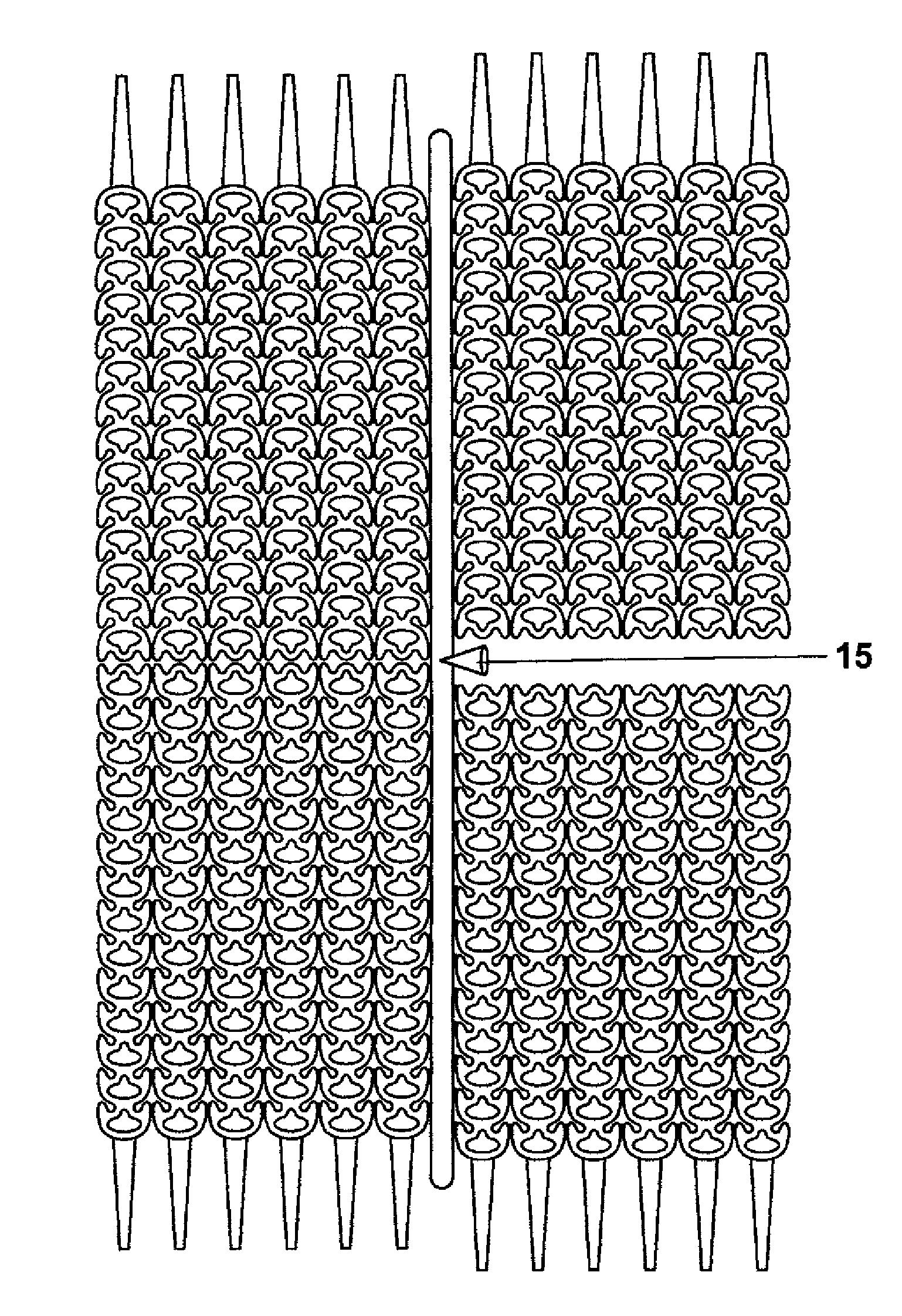
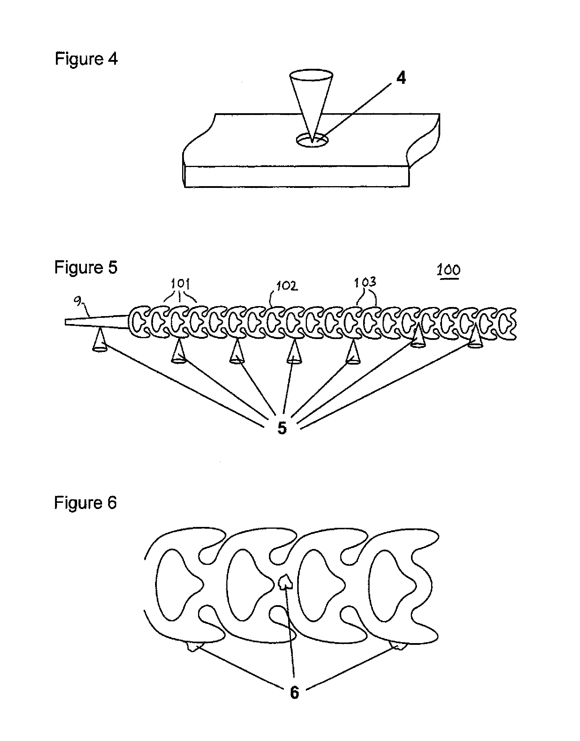
[0036]FIG. 8 illustrates an embodiment of the invention in the form of a sheet of six identical tie strips as shown in FIG. 7 of WO 2004 / 108550, laid out side by side. Each tie strip 100 is made of a line of identical loop-shaped cells 101 through which the front end 9 of the strip can be passed, and each cell has rear-facing hooks or latching members to give a latching function. For the strip to be passed easily through a given cell, the thickness (depth) of the strip is small, and likewise the thickness of the cell walls 102 bounding the loops, which might typically be 10-20% of the width of the strip. The strips are typically made of polyurethane or physically similar material.

[0037]A sprue rod 10 at one side of the sheet illustrates the position of the runner during the moulding process, the runner typically having a main feed point 15 half-way along its length. The melt thus flows from right to left in the drawing through the sheet of strips. The mould walls between the closest...


PUM

PropertyMeasurementUnit
lengthaaaaaaaaaa
Shore hardnessaaaaaaaaaa
widthsaaaaaaaaaa

Abstract

A sheet of cellular tie strips, where each strip is composed of a series of unit cell portions connected end-to-end, is formed in a single molding process. Lateral webs join one or more strips side-by-side to form a sheet such that each strip can be readily separated by tearing, stamping, cutting, leaving only a very thin vestige which does not interfere with the tying of the strips in use.

Description

[0001]The present invention relates to the production of continuous-chain tie strips as used, for example, as cable ties or horticultural plant ties.BACKGROUND OF THE INVENTION[0002]Numerous forms of plastic tie strip are described in the prior art with many varieties being manufactured by injection-moulding from suitable polymer materials. Cable ties (e.g. U.S. Pat. No. 3,186,047, Schwester et al) are a classic example of the technology, as generally shown in FIG. 1. They have a head and a long flat tail, the head having a corresponding slit through which the tail can pass, with a ratchet arrangement to hold the tie in place. They are conventionally produced by standard injection-moulding processes, using either cold or hot runner systems, the latter commonly being the most suitable method for mass production.[0003]The moulding process for these forms of tie strip is normally to fill the mould cavity through a single small orifice cut into the mould known as a gate 1, the gate usua...

Claims


Application Information

Patent Timeline
Patent Type & Authority Patents(United States)
IPC IPC(8): B65D63/10B32B3/24
CPCB29C45/0081Y10T24/1406B29L2007/007B65D63/1018B29C45/0055Y10T24/1498Y10T24/141Y10T428/15
Inventor HARSLEY, ANDREW, JOHN
Owner HARSLEY ANDREW JOHN
Why Eureka
Try Eureka