System and method for combined I/Q generation and selective phase interpolation

a combined i/q and phase interpolation technology, applied in pulse automatic control, pulse generation by logic circuits, pulse techniques, etc., can solve the problems of inherently cumbersome and need for a base clock that operates twice, and achieve the effect of simple and convenient generation

Active Publication Date: 2014-04-29
CADENCE DESIGN SYST INC
View PDF11 Cites 13 Cited by
  • Summary
  • Abstract
  • Description
  • Claims
  • Application Information

AI Technical Summary

Benefits of technology

[0010]It is an object of the present invention to provide a system and method by which I and Q references may be simply and conveniently generated.
[0011]It is another object of the present invention to provide a system and method whereby selectively phased interpolated signals may be conveniently generated with respect to the I and Q signal references.

Problems solved by technology

Unfortunately, generating I and Q references (and its Ī and Q counterparts) using systems and techniques heretofore known is not a trivial matter.
An obvious disadvantage of this approach to I / Q generation is the need for a base clock that operates twice as fast as the generated I / Q references.
Not only are these approaches inherently cumbersome, requiring numerous extraneous components and measures, they typically generate just one output, either the I reference or Q reference, but not both concurrently.
These approaches necessitate power- and area-intensive filters, delay lines, control loops, and the like.

Method used


Image

  • System and method for combined I/Q generation and selective phase interpolation
  • System and method for combined I/Q generation and selective phase interpolation
  • System and method for combined I/Q generation and selective phase interpolation

Examples


Embodiment Construction

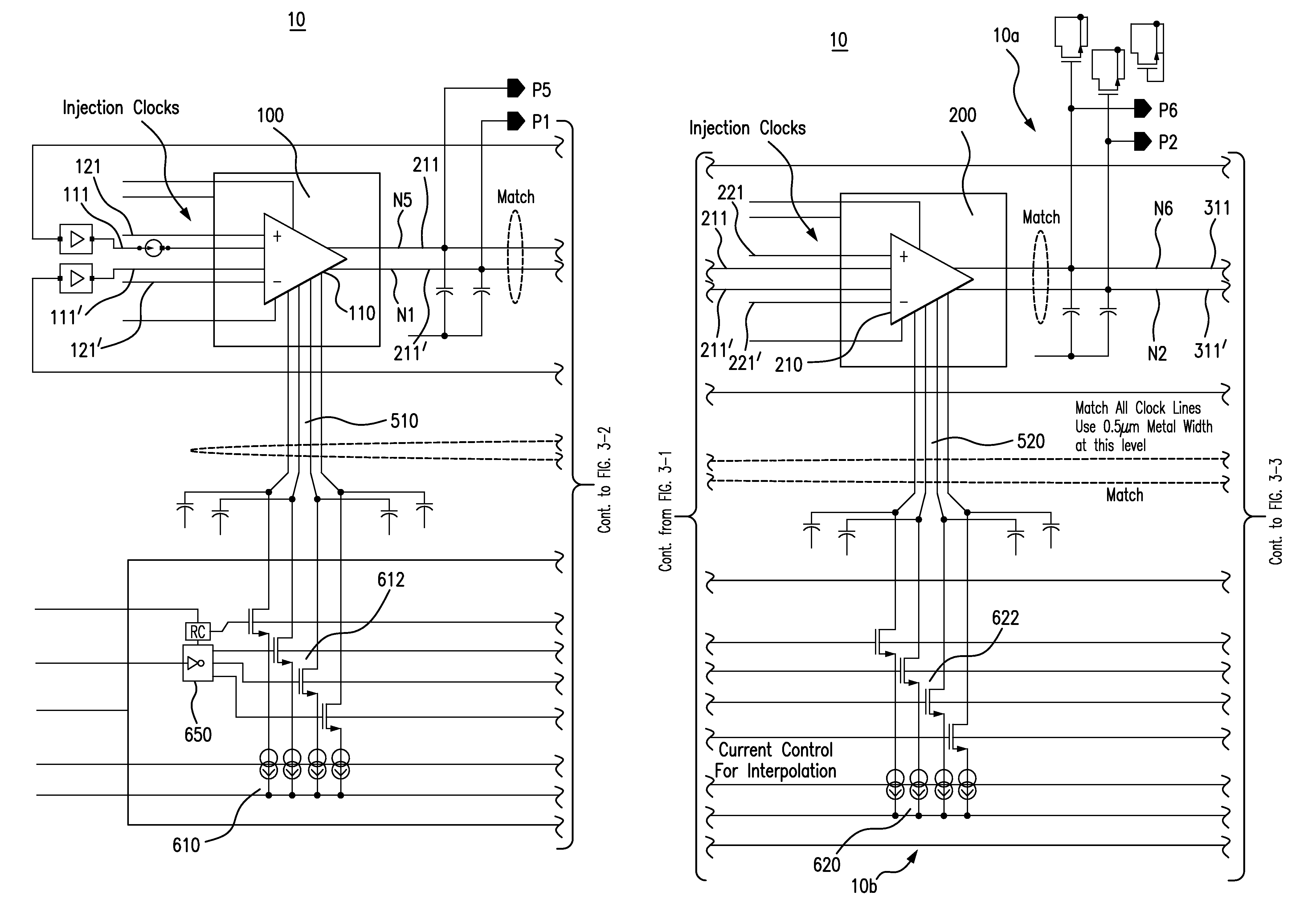
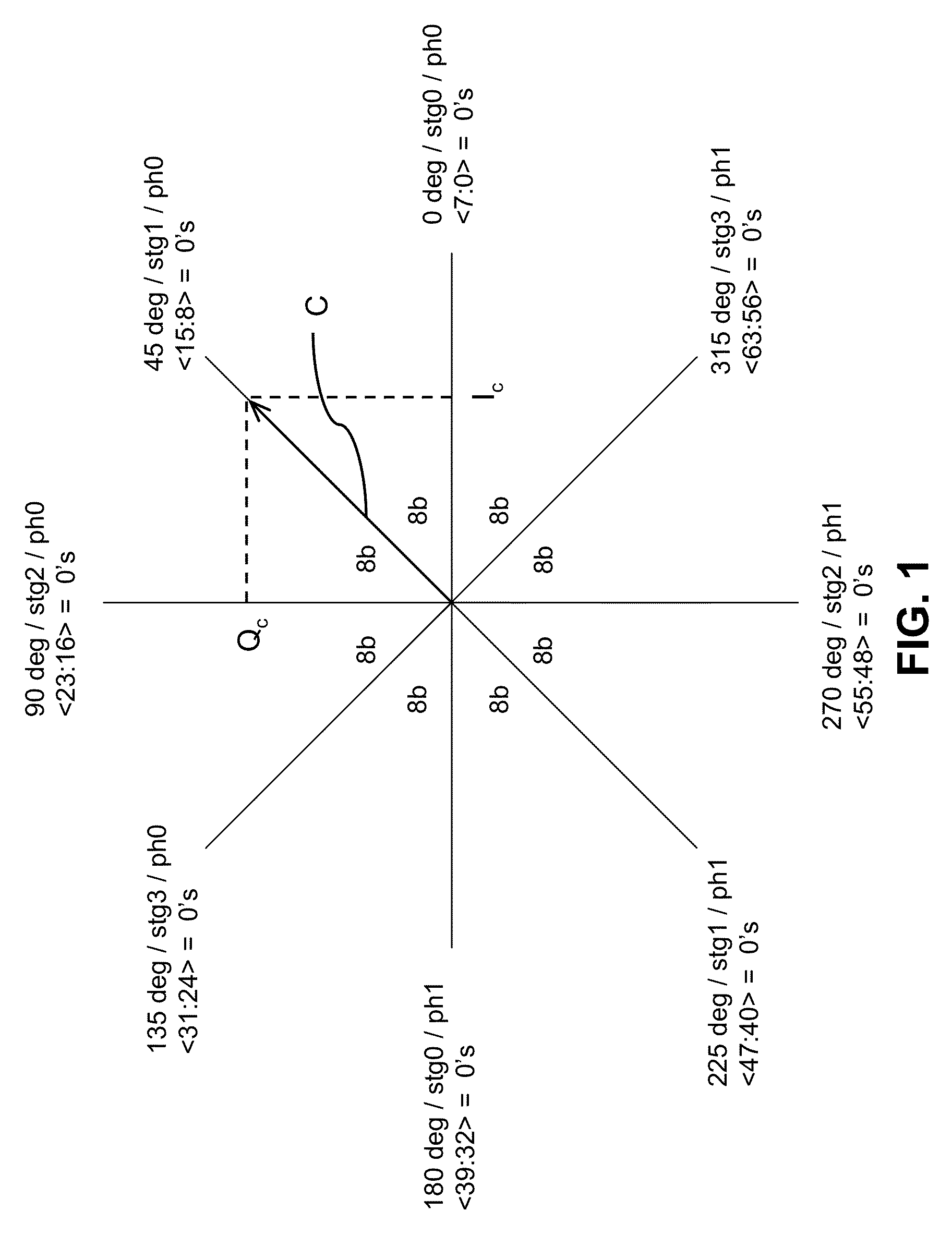
[0021]Generally, a system and method formed in accordance with certain embodiments of the present invention provide for the concurrent generation of I and Q references for a given periodic input signal by injection locking a ring oscillator signal thereto. Further, the system and method provide for the selective adjustment of at least the I reference in relative phase position to accommodate phase interpolation based thereon. The corresponding Q, Ī, Q references, as well as any other phase references of interest, follow from the selectively adjusted I reference.

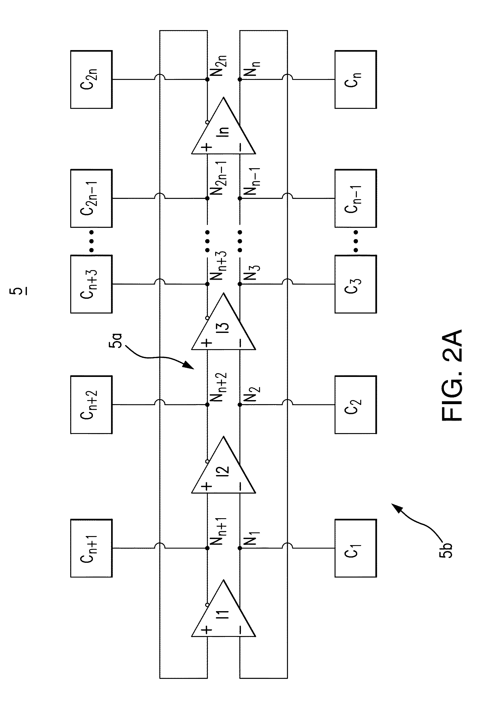
[0022]Referring for illustrative purposes to the highly simplified block diagram of FIG. 2A, a system 5 formed in accordance with one exemplary embodiment of the present invention generally includes a ring oscillator portion 5a and a signal injection portion 5b. Portion 5a is suitably formed with much of the features of a ring oscillator circuit known in the art, which incorporates an odd number of state inversions in a close...


PUM


Abstract

A system and method are provided for combined generation of I and Q signal references according to a periodic input signal and selective phase interpolation of an output signal with reference thereto. A ring oscillator portion generates an oscillator signal, and includes a plurality of delay stages interconnected in cascade to collectively execute an odd number of signal state inversions within a closed loop. The delay stages establish at respective nodes defined therebetween correspondingly delayed oscillator signal versions, successively shifted in phase by a predetermined phase difference. A signal injection portion selectively applies to at least one node of the ring oscillator portion a current bias according to the periodic input signal, and selectively adjusts each current bias in amplitude. The oscillator signal is thereby frequency locked to the periodic input signal, defining I / Q references with respect to the delayed oscillator signal version established at the current biased node.

Description

BACKGROUND OF THE INVENTION[0001]The subject system and method are generally directed to the combined generation of In-phase (I) and Quadrature (Q) reference signals for a periodic input signal, and of selectively phase interpolated signals based on the same. More specifically, the subject system and method are directed to the injection locked generation of such signals in phase adjustable manner.[0002]Sinusoidal and other such periodic signals find wide use for clocking and other purposes in a vast range of applications. A sinusoidal signal of certain frequency may be represented in a number of ways. For instance, it may be represented in polar form, with its value at any instant being defined as a phase vector, or phasor, having certain amplitude and phase offset angle values. A rotation of the phase vector one (360°) revolution about a point of origin then delineates the full range of instantaneous values described during one cycle of the sinusoid signal.[0003]When the periodic s...

Claims


Application Information

Patent Timeline
Patent Type & Authority Patents(United States)
IPC IPC(8): H03K3/03
CPCH03K5/135H03K3/0322H03K2005/00052H03K3/03
Inventor NAVIASKY, ERICMOSCONE, CHRISVIJAYARAGHAVAN, RAJAGOPALHEILMANN, BENJAMIN LOUIS
Owner CADENCE DESIGN SYST INC
Why Eureka
Try Eureka