High-order harmonic device of cavity filter

a cavity filter and harmonic device technology, applied in the direction of resonators, electrical equipment, waveguides, etc., can solve the problems of invalid received signals and the increase of interference between wireless signals in the air, so as to suppress the space for transmitting signals, suppress noise, and signal more clearly and less distortion

Inactive Publication Date: 2014-04-29
UNIVERSAL MICROWAVE TECH INC
View PDF3 Cites 3 Cited by
  • Summary
  • Abstract
  • Description
  • Claims
  • Application Information

AI Technical Summary

Benefits of technology

[0010]According to an aspect of the present invention, a partition with a channel is formed above connecting to adjacent cavities on the base, and a lid is penetrated with a plurality of suppressing adjusting elements of which positioning facing the partitions; the partitions and the suppressing adjusting elements can suppress the space for transmitting signals by the high-order harmonic wave, and thus suppress the noise produced by the high-order harmonic wave in order to have signals more clearly and less distorted.
[0011]The other aspect of the present invention is to have a space formed indented in the bottom of the top face of the partition. While having the lid covering the top surface of the base, every suppressing element does not contact the partition during adjustment, thus prevent ineffective filtration caused by the contact between the suppressing element and the partition. Because the repeated adjustment on the suppressing element is not necessary, the adjustment can be easy with less time consumption.

Problems solved by technology

However, with the increased territory and products of the wireless signal, and the bandwidth of the wireless signal and the wireless signals transmitted in the air is also increased, the interference between wireless signals in the air is becoming more severe (referring to FIG. 7) and the received signals can be invalid due to the unclearness and distortion.
Therefore, how to solve the above described defect is the priority issue for the manufacturers in the field.

Method used


Image

  • High-order harmonic device of cavity filter
  • High-order harmonic device of cavity filter
  • High-order harmonic device of cavity filter

Examples


Embodiment Construction

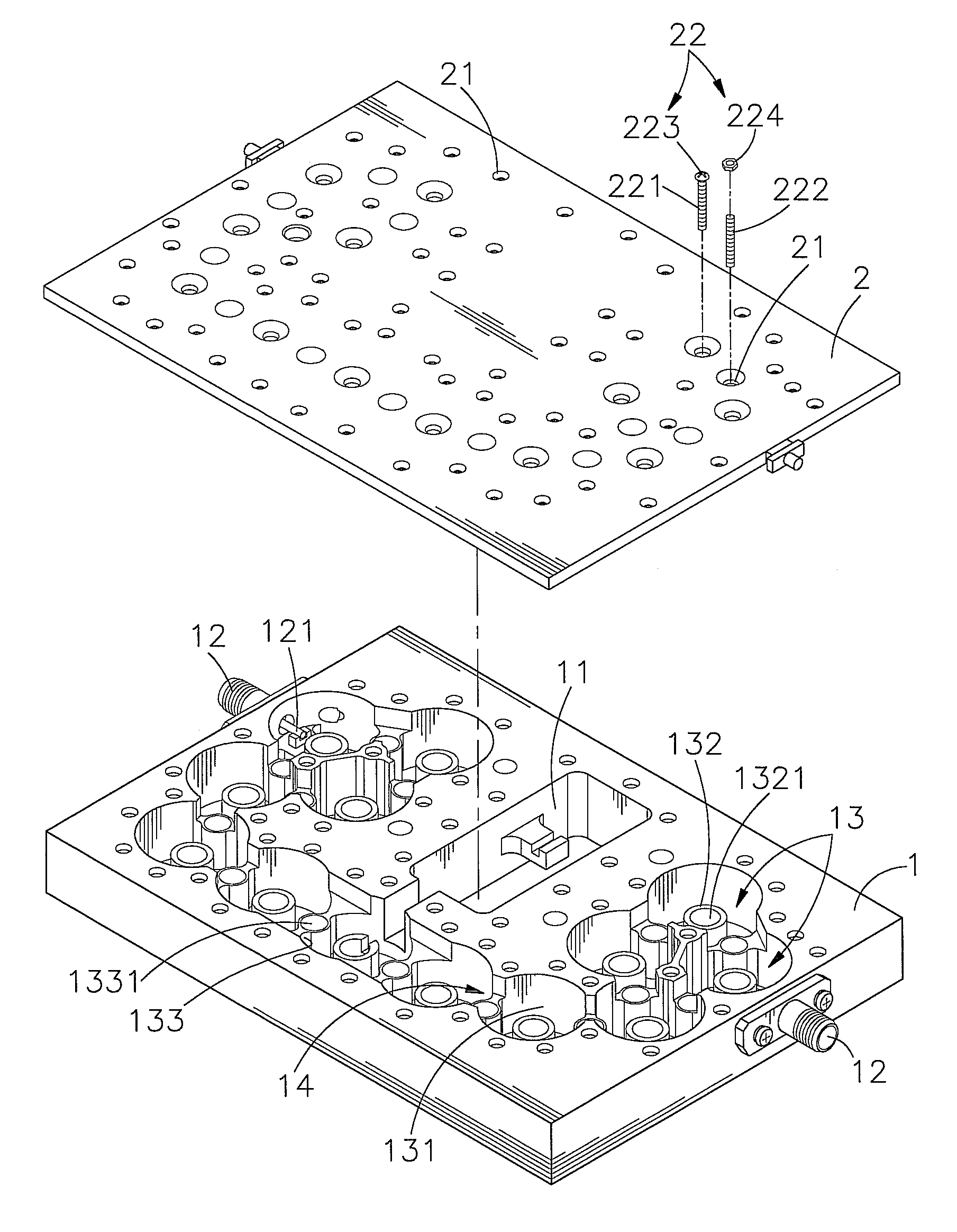
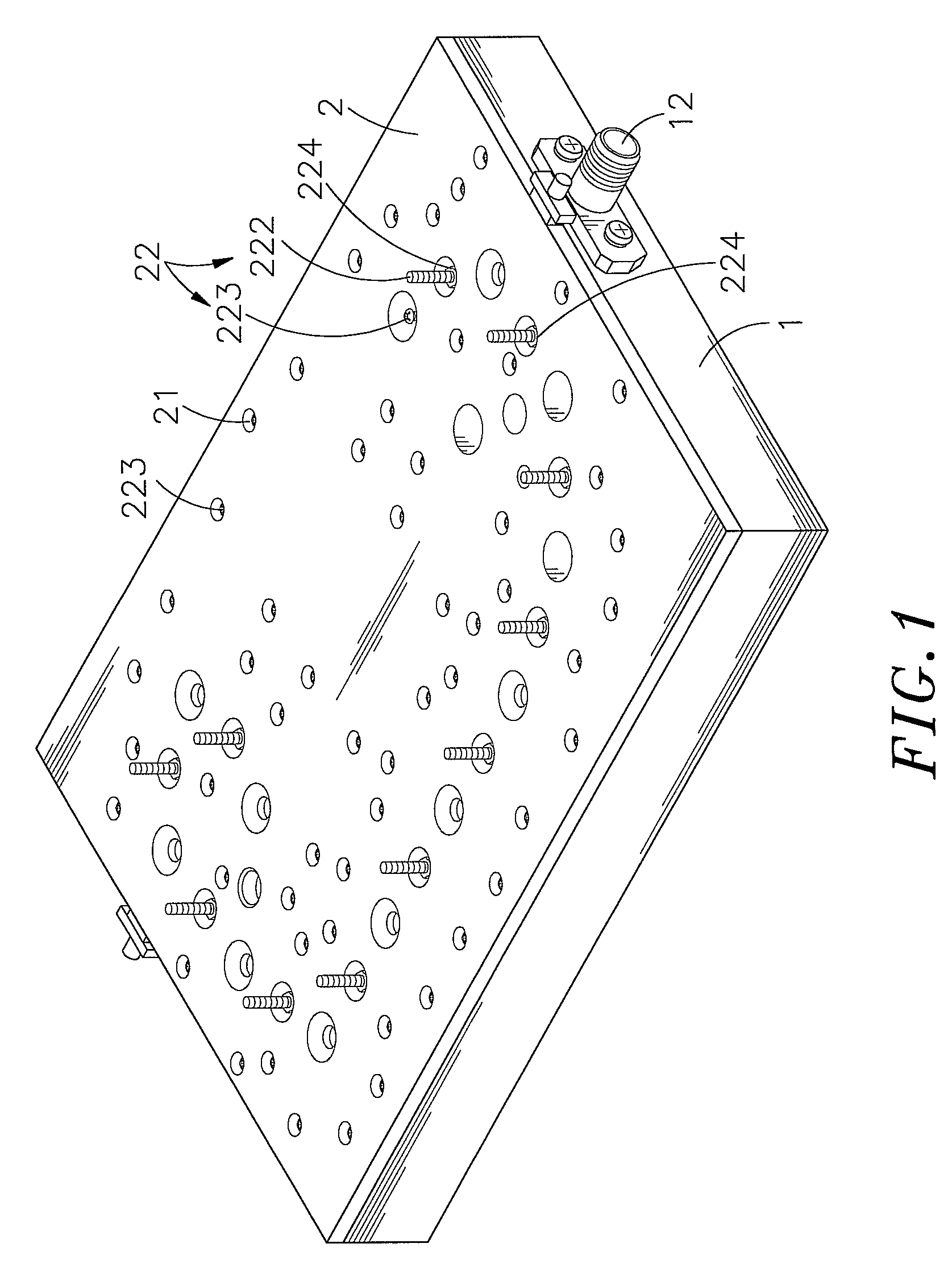
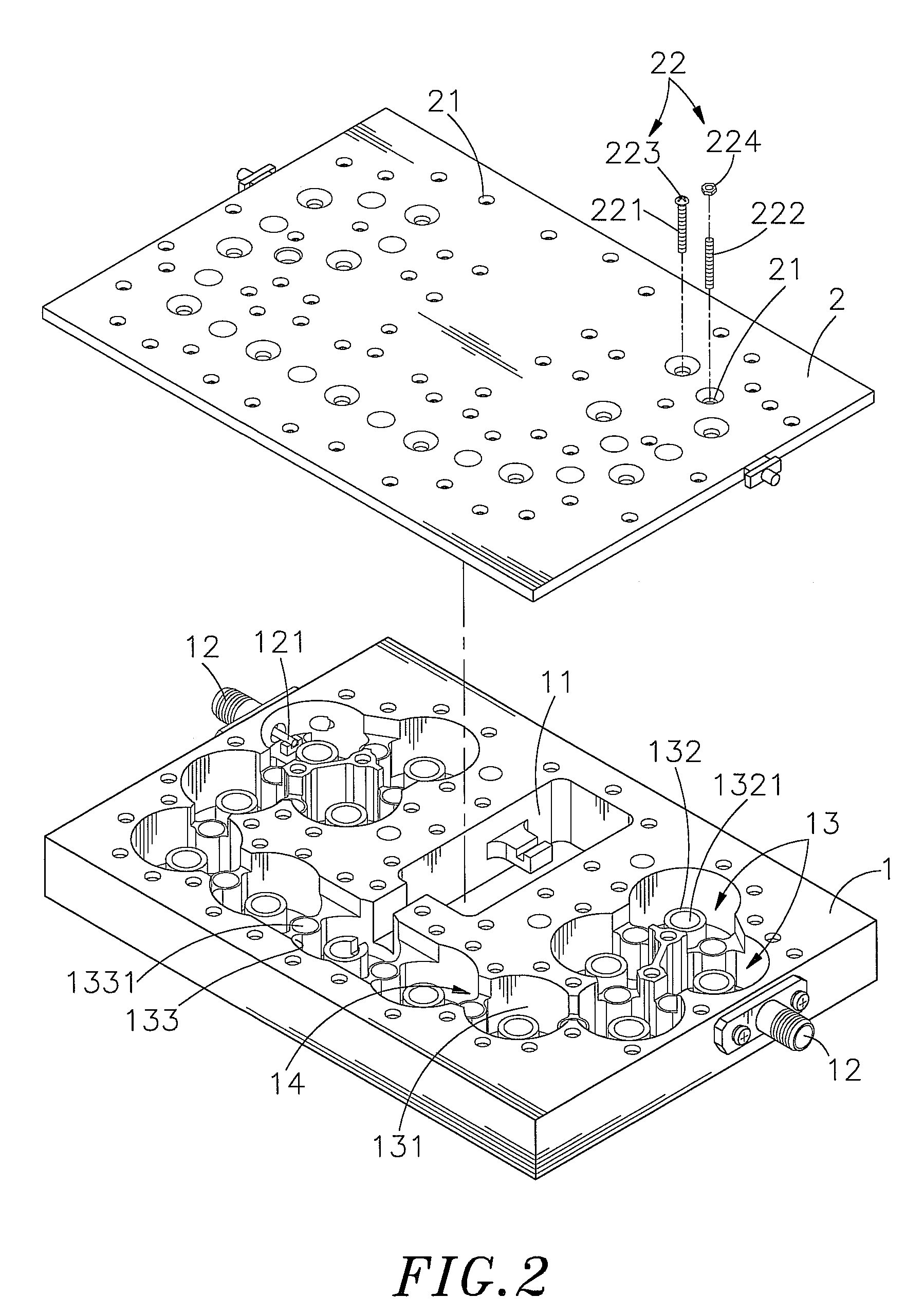
[0019]FIGS. 1, 2, 3 and 4 are an elevational, an exploded view, an elevational view and an elevational view of the base according to a preferred embodiment of the present invention. The high-order harmonic device of a cavity filter comprises a base 1 and a lid 2 covering the base 1.

[0020]The base 1 has a through groove 11 connecting the upper and the lower portion of the base 1, and a plurality of output terminals 12 positioned on the sidewall of the base 1. The output terminals 12 have metallic conductor 121, and the base 1 has a resonance space 13 formed indented for fitting the metallic conductor 121 and extend in a bent fashion go connect to the through groove 11. The resonance space 13 has a plurality of connected chambers 131 having resonant element 132 protruding at the bottom side, and of every chamber 132 has a groove 1321 from the indented downwardly extending from the top side thereof. Each adjacent chamber 131 has a partition 133 forming a channel 14 between the two side...


PUM


Abstract

A high-order harmonic device of a cavity filter including a base and a lid cover the base is disclosed. The base has a through groove connecting to an upper and a lower portion. The base has a plurality of output terminal with metallic conductor extending into the inner side formed on the surface of the sidewall. The base has resonance space formed indented to receive the metallic conductor and extending to connect to the through groove. The lid has a plurality of threading holes formed corresponding to chambers and partitions received with adjusting elements for height adjustment. The adjusting elements has the resonance bars corresponding to every chamber and the suppressing bars corresponding to every partition. By adjusting suppressing bar and the partition to a predetermined distance, the space of the channel for transmitting the high-order harmonic wave can be reduced to suppress noise produced by high-order harmonic wave.

Description

BACKGROUND OF THE INVENTION[0001]1. Field of the Invention[0002]The present invention relates to a high-order harmonic device of a cavity filter. More particularly to a high-order harmonic device having a partition with a channel formed above connecting to adjacent cavities on the base, and a lid penetrated with a plurality of suppressing adjusting elements positioned facing the partitions. The partitions and the suppressing adjusting elements can suppress the space for transmitting signals by the high-order harmonic wave, and thereby suppress noise produced by the high-order harmonic wave in order to have signals more clearly and less distorted.[0003]2. Description of the Related Art[0004]The wireless communication is essential in the modern communication industry, for instance, in the broadcasting, wireless phone, mobile phone, Bluetooth, global positioning system (GPS), wireless network etc, wireless communication is applied everywhere in our daily life. The antenna technology pl...

Claims


Application Information

Patent Timeline
Patent Type & Authority Patents(United States)
IPC IPC(8): H01P1/205H01P7/04
CPCH01P7/04H01P1/205H01P1/2053
Inventor LEE, CHIEN-CHIHHSU, WEI-CHINLIU, HSIEN-WEN
Owner UNIVERSAL MICROWAVE TECH INC
Why Eureka
Try Eureka