Organic-inorganic hybrid solar cell

a solar cell and organic-inorganic technology, applied in the field of organic-inorganic hybrid solar cells, can solve the problems of low efficiency and stability, deterioration of stability, and change of properties, and achieve the effects of reducing the phenomenon of lattice spacing, improving interfacial characteristics, and enhancing device stability

a solar cell and organic-inorganic technology, applied in the field of organic-inorganic hybrid solar cells, can solve the problems of low efficiency and stability, deterioration of stability, and change of properties, and achieve the effects of reducing the phenomenon of lattice spacing, improving interfacial characteristics, and enhancing device stability

US20180211791A1Active Publication Date: 2018-07-26LG CHEM LTD

Image

  • Organic-inorganic hybrid solar cell
  • Organic-inorganic hybrid solar cell
  • Organic-inorganic hybrid solar cell

Examples


example 1

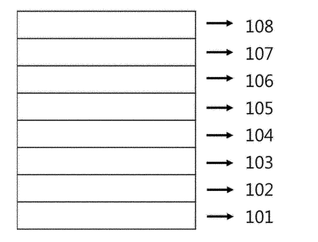
[0126]An organic substrate (40 Ω / sq) coated with indium tin oxide (ITO) was washed sequentially with acetone and isopropyl alcohol (IPA) for 1 hour, respectively, by using an ultrasonic cleaner. An ITO substrate coated with TiO2 (hereinafter, referred to as an electron transporting layer) was manufactured by repeating three times a procedure of spin-coating a solution including titanium dioxide (TiO2) on the ITO substrate, and heat treatment at 150° C. for 30 minutes.

[0127]A yellow solution formed by dissolving 1 mM of lead iodide (PbI2) (purity 99%, Sigma Aldrich Co., Ltd.) in 1 ml of dimethylformamide (DMF) was spin-coated on the electron transporting layer. Thereafter, a first light absorbing layer was formed by spin-coating a solution formed by dissolving 10 mg of CH3NH3I (MAI) in 1 ml of isopropyl alcohol thereon, and performing a heat treatment at 100° C. for 10 minutes.

[0128]Thereafter, a second light absorbing layer was formed by spin-coating 200 μl of a solution, which was ...

example 2

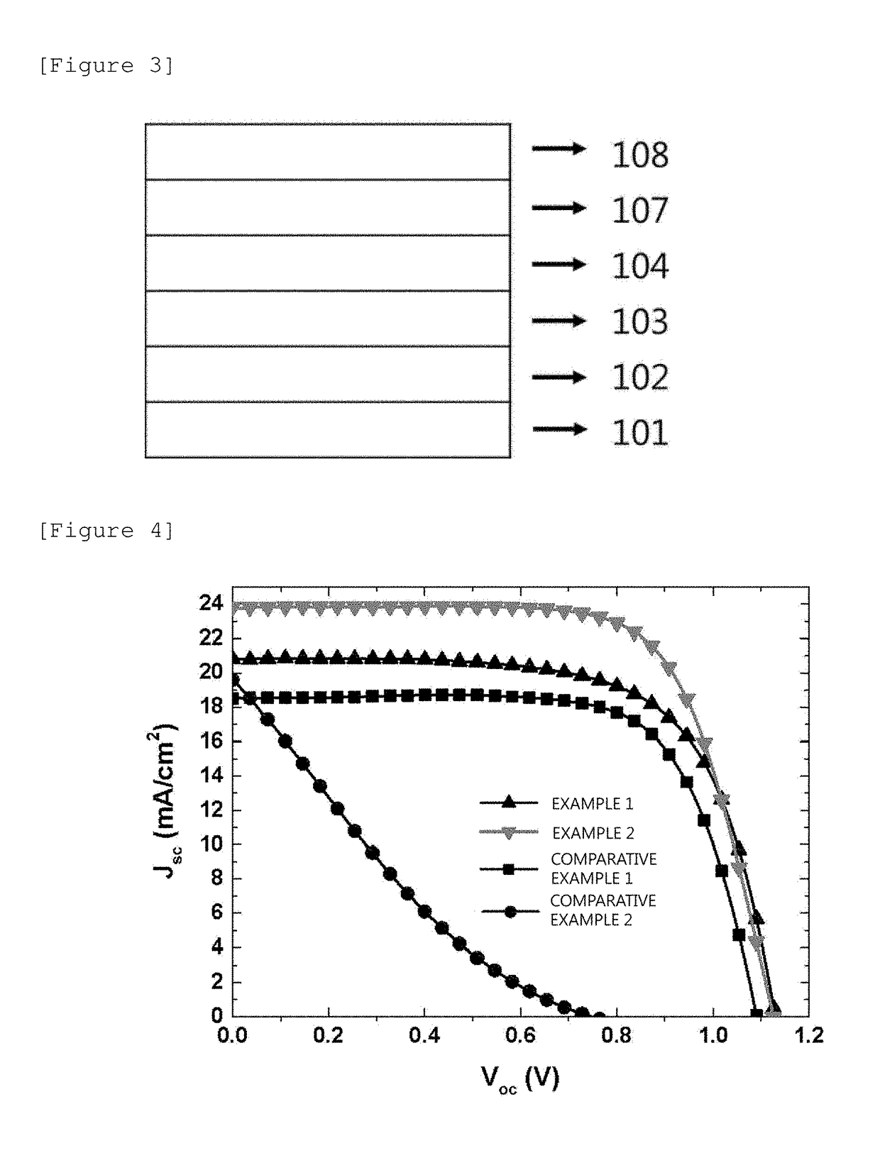
[0132]An organic-inorganic hybrid solar cell was manufactured in the same manner as in Example 1, except that in order to form the second light absorbing layer, 200 μl of a solution formed by mixing (HC(NH2)2)I and CH3NH3I at a molar ratio of 0.7:0.3 and then dissolving the mixture in 1 ml of isopropyl alcohol was spin-coated on the upper portion of the first light absorbing layer.


PUM


Abstract

The present specification relates to an organic-inorganic hybrid solar cell.

Description

TECHNICAL FIELD[0001]This application claims priority to and the benefit of Korean Patent Application No. 10-2016-0089317 filed in the Korean Intellectual Property Office on Jul. 14, 2016, the entire contents of which are incorporated herein by reference.[0002]The present specification relates to an organic-inorganic hybrid solar cell.BACKGROUND ART[0003]In order to solve the global environmental problems caused by the depletion of fossil fuels and the use thereof, studies have been actively conducted on alternative energy sources, which may be regenerated and are clean, such as solar energy, wind power, and water power. Among them, interests in solar cells which change electric energy directly from the sunlight have been greatly increased. Here, the solar cell means a cell which produces current-voltage by using a photovoltaic effect of absorbing photoenergy from the sunlight to generate electrons and holes.[0004]Organic-inorganic hybrid perovskite materials have recently drawn att...

Claims


Application Information

Patent Timeline
26 Jul 2018
Publication
US20180211791A1
IPC
H01G9/20; H01L51/44; H01L51/42
CPC
H01G9/2018; H01L51/442; H01L51/4246; H01L51/0077; H01L51/006; H01L51/0056; H01L51/0067; Y02E10/549
Inventors
KIM, SEIYONG; PARK, SANG JUN