
Earphone

a technology for earphones and earphones, applied in the field of earphones, can solve the problems of impracticality for vibrating plates, small drive energy of earphone drivers, and limit the improvement of acoustic characteristics, etc., and achieve the effect of reducing pressure, improving fidelity of vibration in the bass range caused by large back pressure, and reducing frequency rang

Active Publication Date: 2014-04-29
AUDIO-TECHNICA
View PDF18 Cites 104 Cited by
  • Summary
  • Abstract
  • Description
  • Claims
  • Application Information

AI Technical Summary

Benefits of technology

[0011]The earphone according to the present invention is provided with the hollow casing separately from the housing which accommodates the driver unit such that the internal space of the casing and the rear side of the housing communicate through the connecting channel, allowing the space adjacent the rear side of the vibrating plate to expand and reduce the pressure on the rear side during vibration. As a result, the vibrating plate can vibrate faithfully according to input sound signals, and the fidelity of the vibration in the bass range caused by large back pressure is significantly improved, leading to the expansion of the reproducible area in the bass range.
[0012]A possible countermeasure to expand the reproducible low-frequency range is to provide a hole enabling the space adjacent the rear side of the vibrating plate to communicate with the outer space, like conventional embodiments shown in FIGS. 10 and 11; however, noise leaking through the hole makes it an unfavorable approach.
[0013]The earphone according to the present invention, which is provided with a hollow casing separately from the housing, can reproduce the lower frequency range in a balanced manner. Expansion of the internal space by enlarging the casing enables further lower frequencies to be reproduced. Accordingly, it is preferred that the casing be as large as possible. An earphone provided with a large casing is more likely to fall out of the ear of the user because of its unbalanced weight.
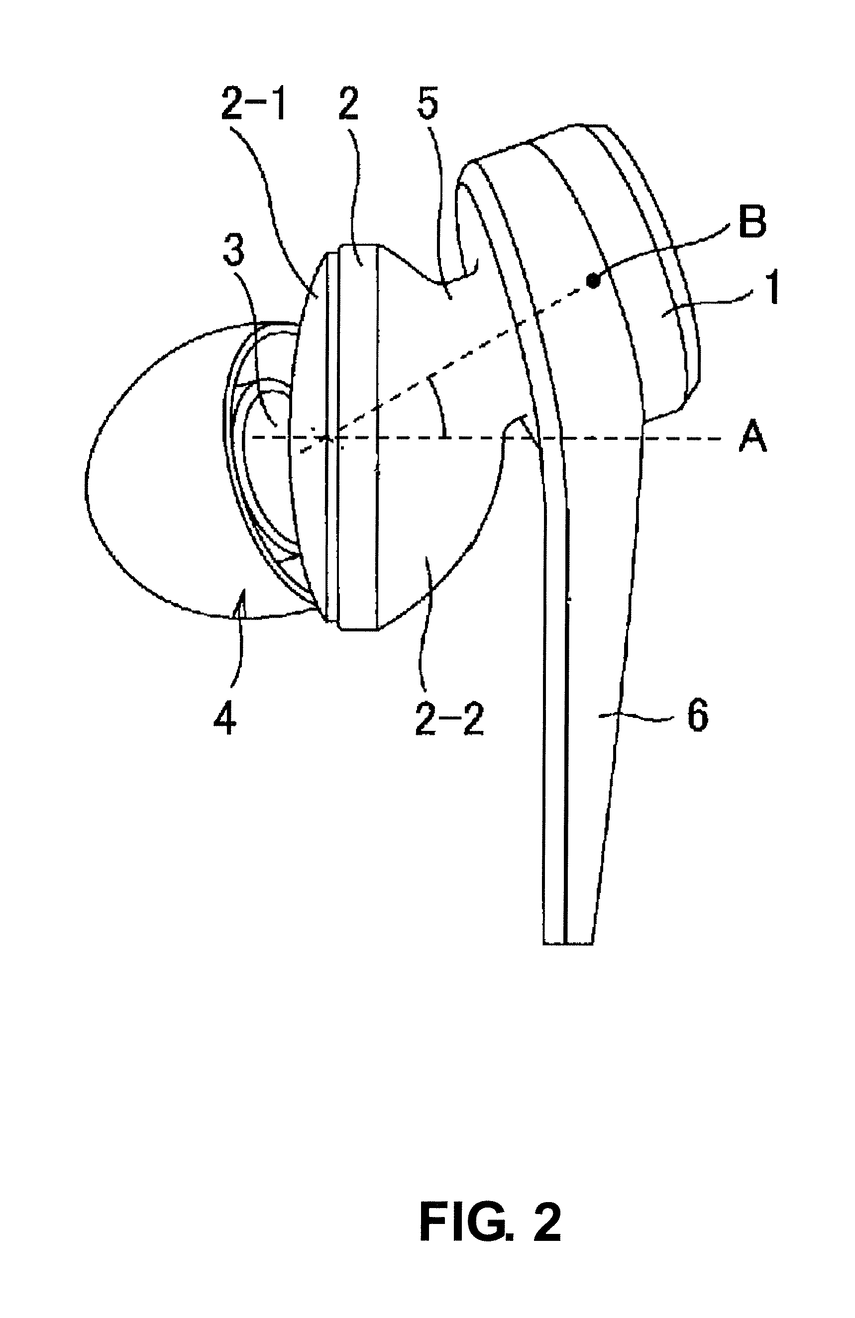
[0014]Regarding this, according to another embodiment of the invention, since the casing is configured to be positioned diagonally upwards from the housing in use, the force to turn the housing by the load applied to the casing is too weak to cause the earphone to fall out of the ear of the user. Furthermore, according to another embodiment of the invention, the housing is configured to be urged to the cavity defined by a tragus, anti-tragus, and ear concha of the user, resulting in the housing in use advantageously maintained more stable.

Problems solved by technology

Unfortunately, such a configuration shown in FIG. 11 restricts the shape and thickness of the driver unit 103, and thus the expansion of the internal volume of the bass compensating pipe 112, imposing limitations on improved acoustic characteristics, especially of the bass range.
Unfortunately, the drive energy from the earphone driver is essentially so small that it is impractical for the vibrating plate 204 for bass compensation to be resonated by a vibration caused by the vibrating plate of the driver unit.
Even if the vibrating plate 204 for the bass compensation can be resonated, only the resonant frequency range is emphasized, so that well-balanced sound cannot be reproduced over the entire frequency range, or otherwise the driver needs to be driven at such large power as may harm an ear of a user.
Furthermore, the vibrating plate 204 for the bass compensation provided inside the second housing 202 is a factor of high production costs.

Method used


Image

  • Earphone
  • Earphone
  • Earphone

Examples


Embodiment Construction

[0027]An earphone according to an embodiment of the present invention will be described with reference to the following drawings.

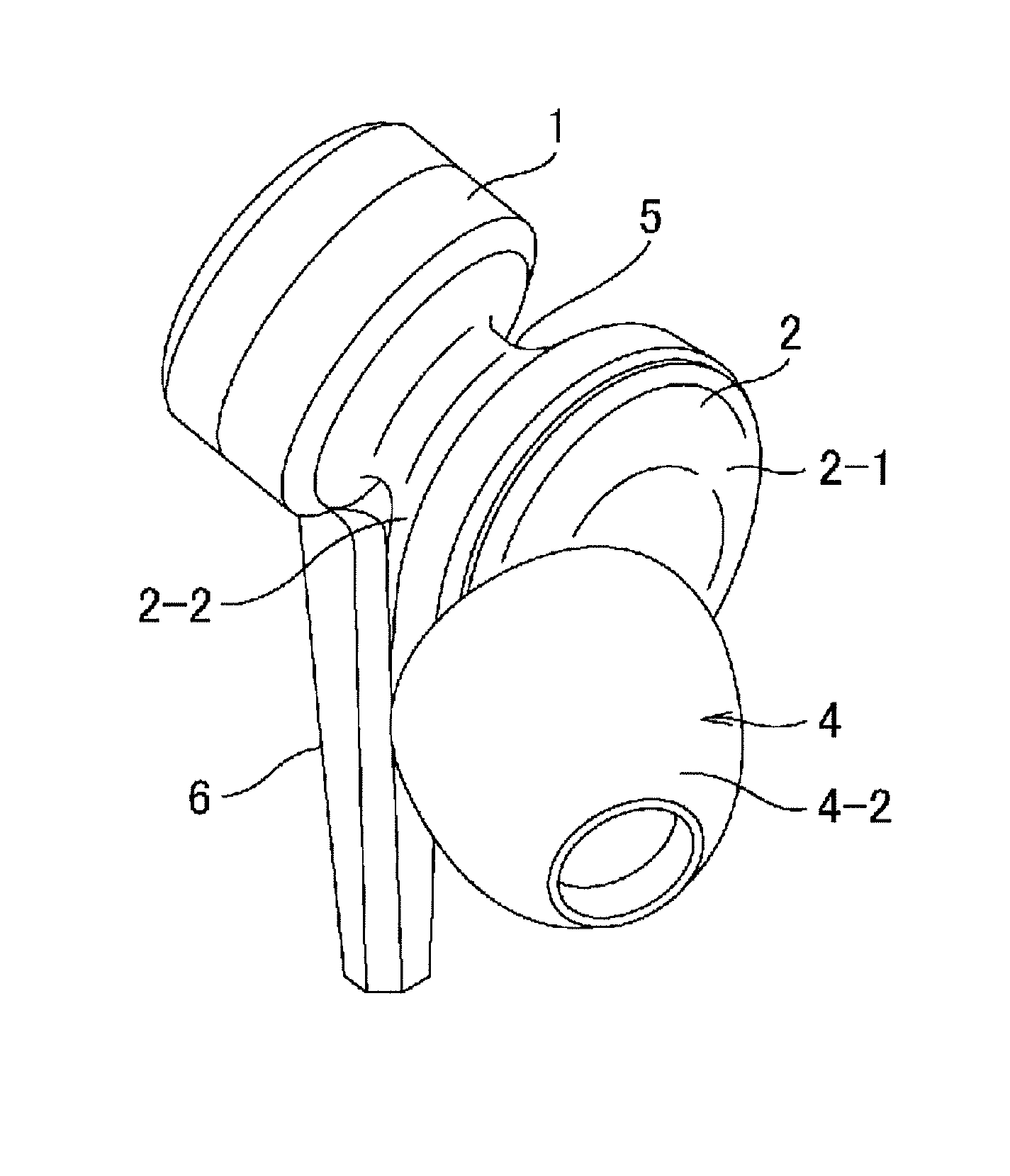
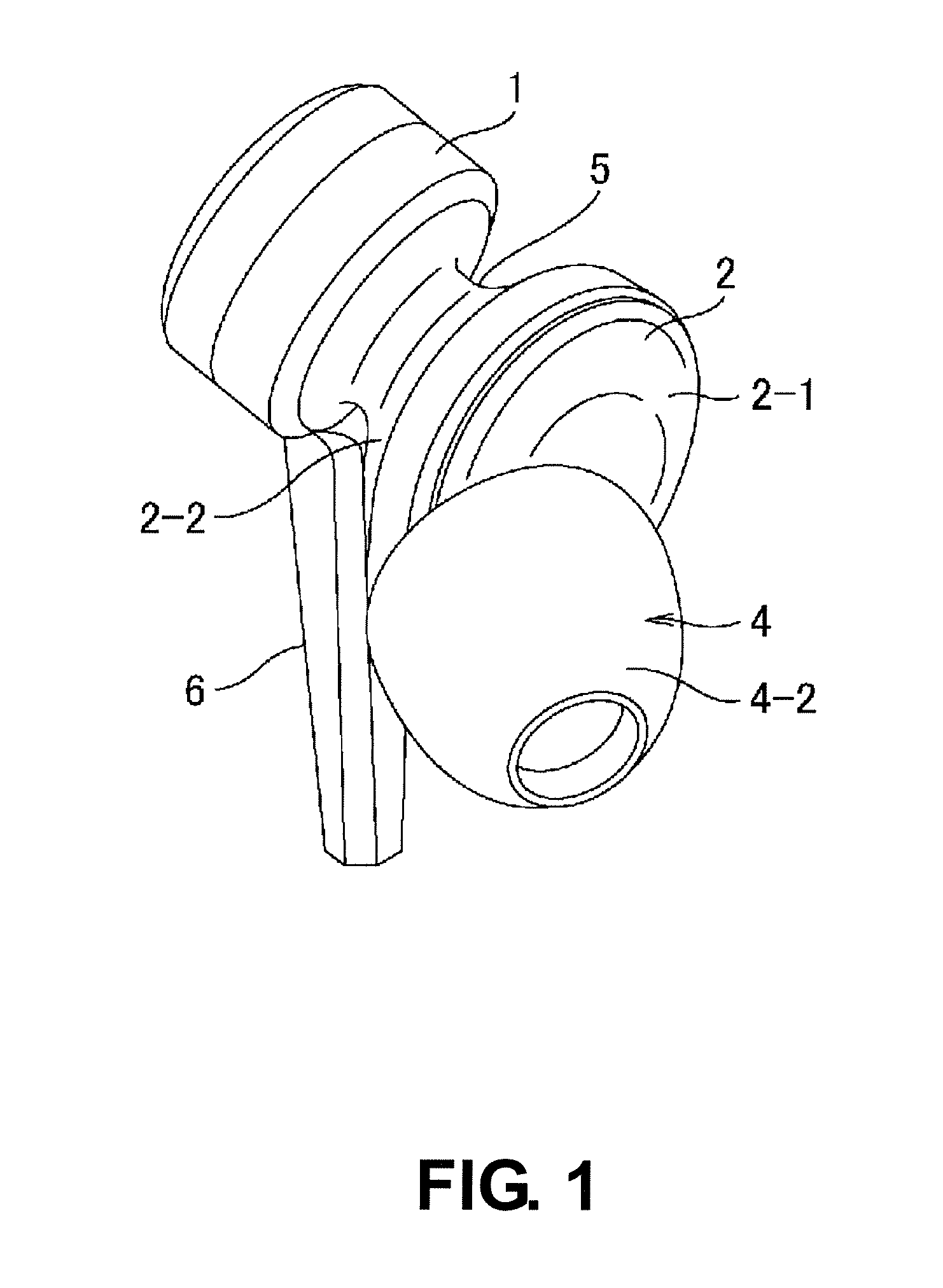
[0028]In FIGS. 1 to 4, the earphone includes the following major components: a housing 2, a casing 1, a connecting channel 5 connecting the housing 2 and the casing 1 integrally, a sound emitting tube 3, and an ear piece 4. The housing 2 is originally hollow and accommodates a driver unit (not shown) inside of the hollow portion. The housing 2 comprises a bowl-shaped rear face 2-2 and a planar circular front face 2-1. The casing 1 is a hollow member different from the housing 2 and has a cylindrical shape with its both end faces closed. The term “hollow” refers to the state being “empty in the interior” that accommodates no movable member such as a vibrating plate for bass compensation. The connecting channel 5 has a cylindrical shape and connects the rear face 2-2 of the housing 2 and the one end face of the casing 1 such that the housing 2 is in communic...


PUM


Abstract

The earphone includes a driver unit; a housing accommodating the driver unit, the housing having a front face serving as a sound emitting surface and a bowl shaped rear face; a hollow casing provided separately from the housing, the casing being configured to increase an internal volume adjacent to the rear side of a vibrating plate and to reduce the back pressure of the vibrating plate; and a connecting channel connecting the rear face of the housing and the casing such that the housing is in communication with the internal space of the casing, in which the housing includes a sound emitting tube protruding from the front face thereof so as to be fitted into an external auditory meatus.

Description

TECHNICAL FIELD[0001]The present invention relates to an earphone used as an acoustic device, and in particular an earphone that includes a driver unit having a vibrating plate with a reduced backpressure and thus improved acoustic characteristics.BACKGROUND ART[0002]Among traditional earphones used as acoustic devices, an earphone having a hole provided at a portion of a housing thereof and provided with an acoustically resistive member to adjust acoustic characteristics is proposed as an example for improving acoustic characteristics. A typically traditional earphone has a structure shown in FIG. 10. In FIG. 10, a bowl-shaped housing 102 accommodates a driver unit 103 therein and an opening 110 for sound emission at the front face. The driver unit 103 has a yoke 104 into which a disk-shaped magnet 105 is affixed, and a disk pole piece 106 affixed on the magnet 105. The peripheral edge of a vibrating plate 107 is supported by the inner periphery of the housing 102, and the vibratin...

Claims


Application Information

Patent Timeline
Patent Type & Authority Patents(United States)
IPC IPC(8): H04R25/00
CPCH04R1/345H04R1/1016H04R1/10H04R1/28
Inventor OZAWA, HIROMICHI
Owner AUDIO-TECHNICA
Learn More