
Apparatus for the injection moulding of containers in plastic material

a technology for plastic materials and containers, applied in the field of apparatuses for the injection moulding of containers in plastic materials, can solve the problems of increasing production costs, obvious waste of materials and energy, and inability to guarantee the centring between the male element and the female matrix die, so as to reduce the thickness of the inter-space, reduce the number of rejects, waste and manufacturing costs

Active Publication Date: 2014-05-06
LAMEPLAST
View PDF4 Cites 0 Cited by
  • Summary
  • Abstract
  • Description
  • Claims
  • Application Information

AI Technical Summary

Benefits of technology

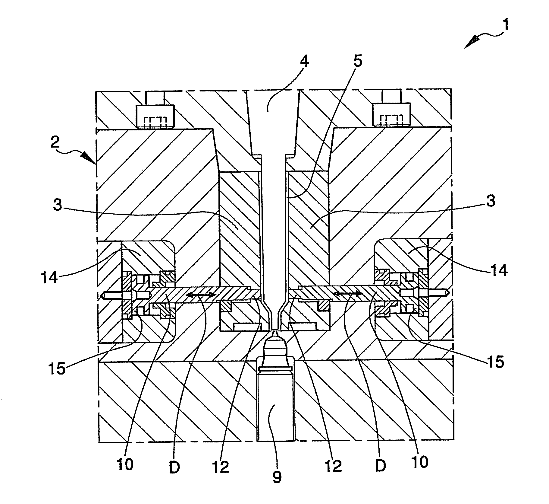
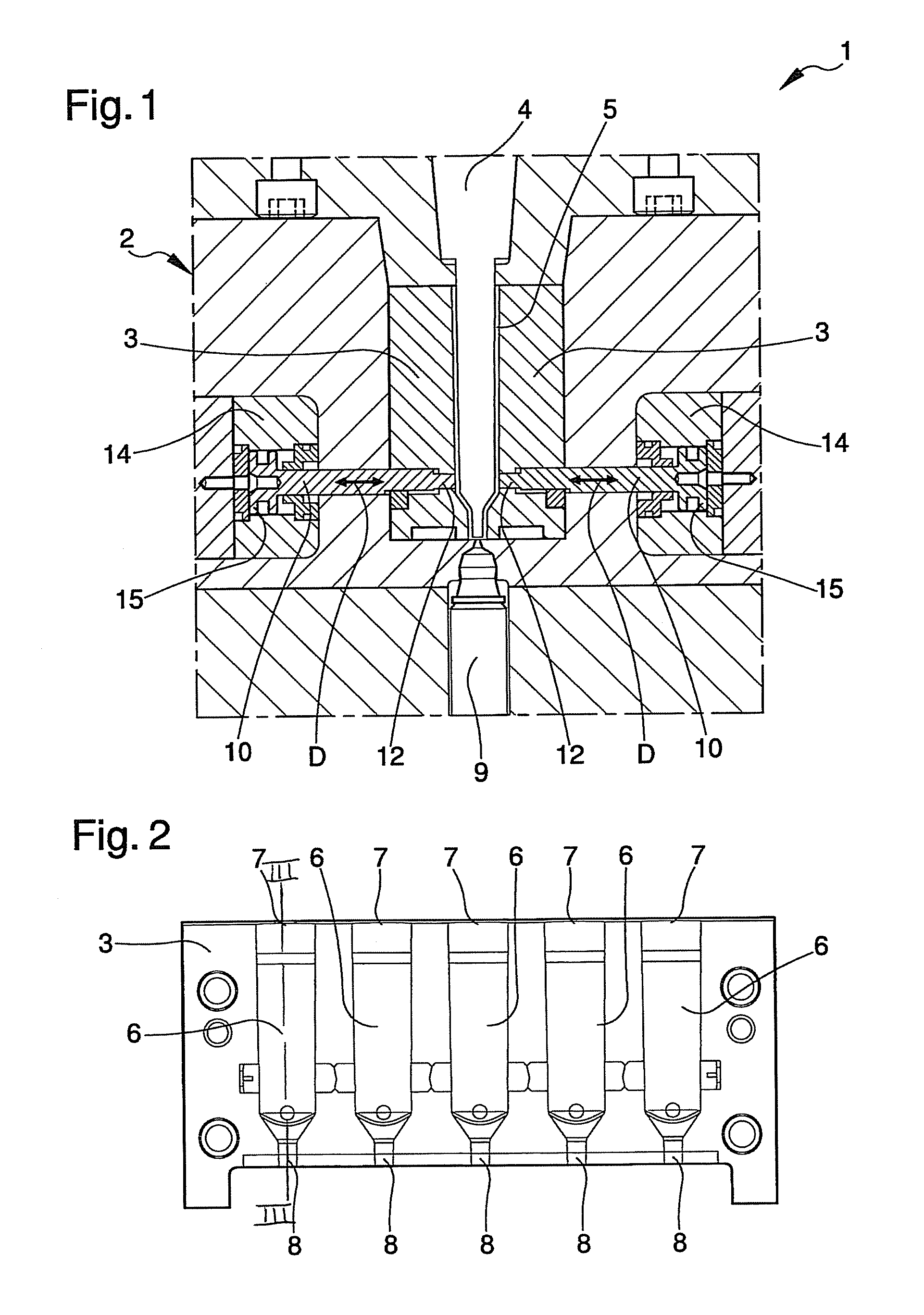
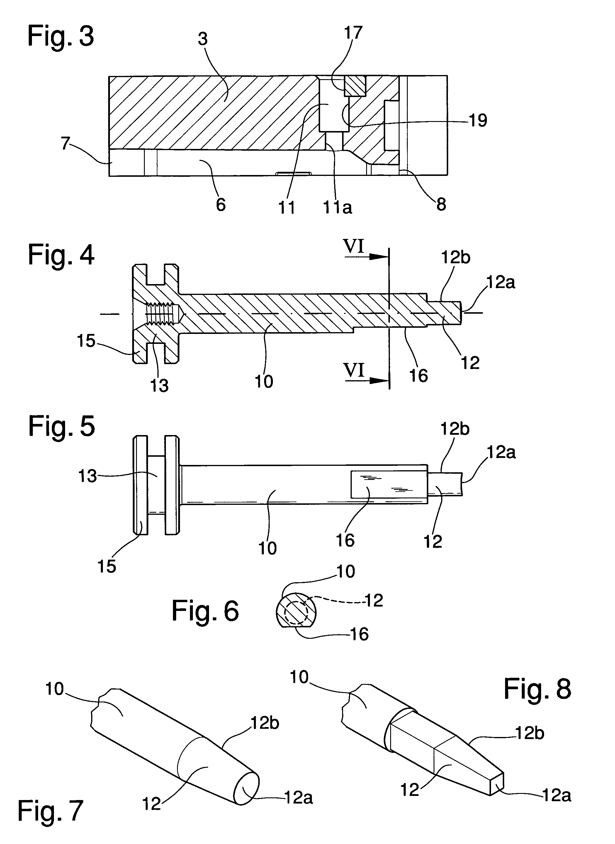
[0025]The main aim of the present invention is to eliminate the drawbacks complained of above affecting the moulds of known type and to provide an apparatus for the injection moulding of containers in plastic material which allows reducing the thickness of the inter-space defined between male and female within the required tolerance interval, to successfully centre the male elements with respect to the corresponding female matrix die, to maintain the males in aligned configuration during container moulding and, at the same time, considerably reduce the number of rejects, waste and manufacturing costs, thereby becoming more competitive from an economic viewpoint.
[0026]Another object of the present invention is to provide an apparatus for the injection moulding of containers in plastic material which allows overcoming the mentioned drawbacks of the state of the art within the ambit of a simple, rational, easy and effective to use as well as low cost solution.

Problems solved by technology

The moulds of known type are not without their drawbacks, including the fact that they do not guarantee the centring between the male element and the female matrix die.
Consequently, there is an increase in production rejects and, considering the retrieval of the rejected material is often difficult and costly, this results in obvious wastes of materials and energy, time extensions and increase in production costs.
This particular moulding apparatus is not without its drawbacks however including the fact that the alternate sliding of the stems in the corresponding holes of the matrix die soon determines the arising of serious problems tied to material wear.
The coupling between stems and holes, in fact, is achieved by adopting very narrow tolerances and the sliding is such as to cause fast surface wear, with the formation of small metal scraps which often end up inside the inter-space during moulding.
The containers thus formed therefore have inconvenient metal inclusions inside the walls which are visible from the outside, above all if the plastic material is white or transparent.
These containers inevitably end up by being rejected because not in compliance with the required project specifications from a technical and / or aesthetic and / or hygienic viewpoint.
In this respect, it must be underlined that in the medical, pharmaceutical and / or cosmetic field, the use of containers in imperfect aesthetic conditions produces in users the doubt that the fluid products contained in them have been contaminated and, consequently, their refusal to use them.
The apparatus according to the document US 2001 / 0015512, is also therefore susceptible to further upgrading aimed at reducing the rejects and production times, limiting material and energy waste, and cutting manufacturing costs, with the possibility of lowering the retail prices and making the products more interesting for consumers.

Method used


Image

  • Apparatus for the injection moulding of containers in plastic material
  • Apparatus for the injection moulding of containers in plastic material
  • Apparatus for the injection moulding of containers in plastic material

Examples


Embodiment Construction

[0040]Reference will now be made in detail to the present embodiments of the present invention, examples of which are illustrated in the accompanying drawings, wherein like reference numerals refer to the like elements throughout. The embodiments are described below in order to explain the present invention by referring to the figures.

[0041]With reference to such figures, globally indicated by 1 is an apparatus for the injection moulding of containers in plastic material, which can be both of the thermoplastic, thermosetting and other type again.

[0042]The apparatus 1 shown in the illustrations, e.g., is intended for the moulding of strips of single-dose bottles for pharmaceutical, medicinal and cosmetic products or the like, but different embodiments cannot be ruled out.

[0043]The apparatus 1 comprises a mould 2 which has a female matrix die 3 and at least a corresponding male element 4 that can be coupled together, between the female matrix die 3 and the male element 4, a forming in...


PUM

PropertyMeasurementUnit
angleaaaaaaaaaa
angleaaaaaaaaaa
angleaaaaaaaaaa

Abstract

The apparatus (1) for the injection molding of containers in plastic material comprises a mold (2) having a female matrix die (3) and a corresponding male element (4) that can be coupled to one another, between the female matrix die (3) and the male element (4) being defined a forming inter-space (5) of at least a container, and at least a centering stem (10) for centering the male element (4) with respect to the female matrix die (3), which comprises a first extremity (12) having a locator surface (12a) for the male element (4), is sliding along a sliding direction (D) substantially transversal with respect to the male element (4) inside a corresponding centering hole (11) obtained in the female matrix die (3), and is mobile with reciprocating motion between a backward configuration, in which the locator surface (12a) is substantially arranged in correspondence to the inner surface of the female matrix die (3), and a forward configuration, in which the locator surface (12a) is up fast on the male element (4), the first extremity (12) of the centering stem (10) having a cross section substantially decreasing towards the locator surface (12a).

Description

CROSS-REFERENCE TO RELATED APPLICATIONS[0001]This application claims the benefit of PCT International Patent Application No. PCT / IB2010 / 002248, filed Sep. 10, 2010, and Italian Patent Application No. MO2009A000303, filed Dec. 21, 2009, the disclosures of which are incorporated herein by reference.BACKGROUND OF THE INVENTION[0002]1. Field of the Invention[0003]The present invention relates to an apparatus for the injection moulding of containers in plastic material, such as, e.g., single-dose bottles for pharmaceutical, medicinal and cosmetic products.[0004]2. Description of the Related Art[0005]Moulds are known for moulding containers composed essentially of a female matrix die wherein are obtained one or more cavities inside which can be inserted corresponding male elements, the cavities being in the same number as the containers moulded at each cycle.[0006]Between the inner surface of the above cavities and the outer surface of the relevant male elements an inter-space is defined ...

Claims


Application Information

Patent Timeline
Patent Type & Authority Patents(United States)
IPC IPC(8): B29C45/36
CPCB29C45/36B29C2045/366B29C45/261
Inventor FONTANA, ANTONIO
Owner LAMEPLAST
Learn More