Apparatus for mixing a substance into a medium

Inactive Publication Date: 2014-05-13
ANDRIZ OY
View PDF6 Cites 1 Cited by
  • Summary
  • Abstract
  • Description
  • Claims
  • Application Information

AI Technical Summary

Benefits of technology

[0012]An apparatus has been conceived to improve the mixing efficiency of static mixers so that they can be

Problems solved by technology

Although modern fluidizing chemical mixers are reasonably small, intensifying energy consumption creates needs to decrease the amount of energy used for mixing chemicals.
Although direct steam injection heaters are efficient, fiber suspensions with flocking matter tend to clog the heater, if the suspension is to flow through bends and turns.
Small jets of steam are easily scattered in a viscose suspension and distributed before the steam has a possibility to combine into large bubbles which may generate pressur

Method used


Image

  • Apparatus for mixing a substance into a medium
  • Apparatus for mixing a substance into a medium
  • Apparatus for mixing a substance into a medium

Examples


Embodiment Construction

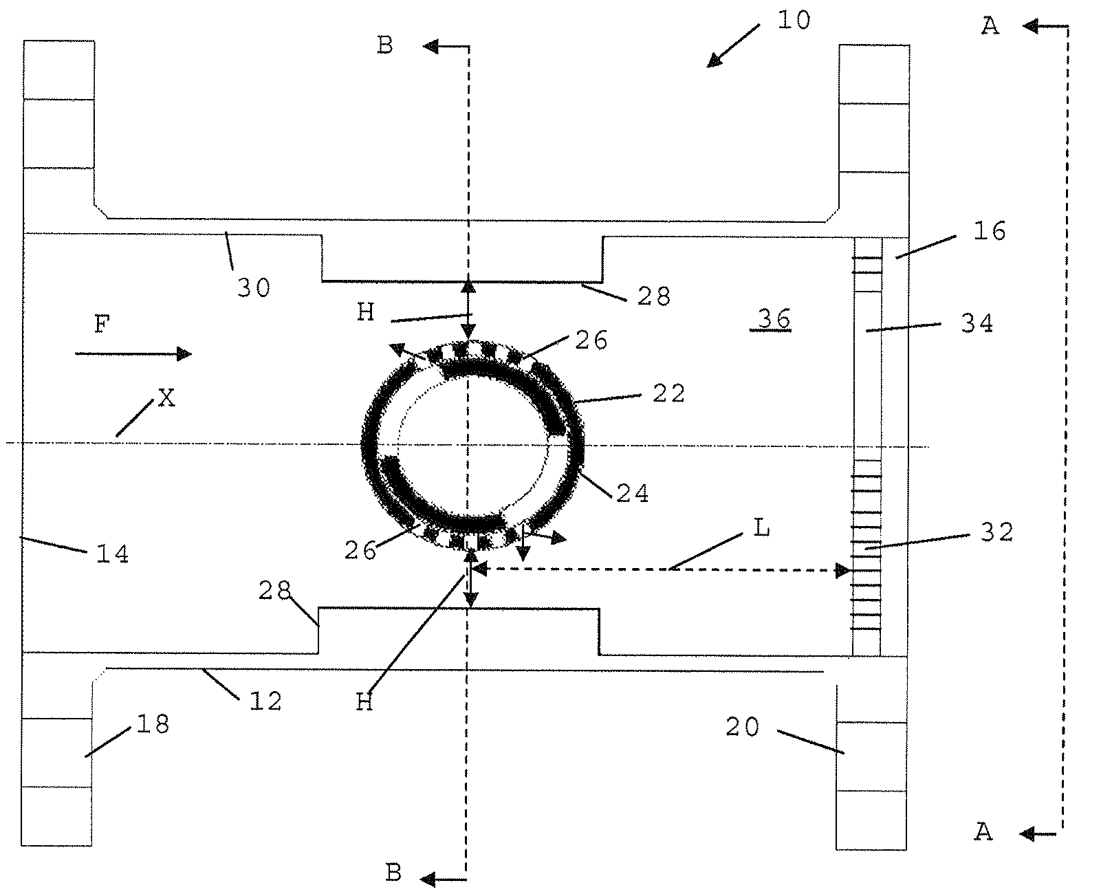
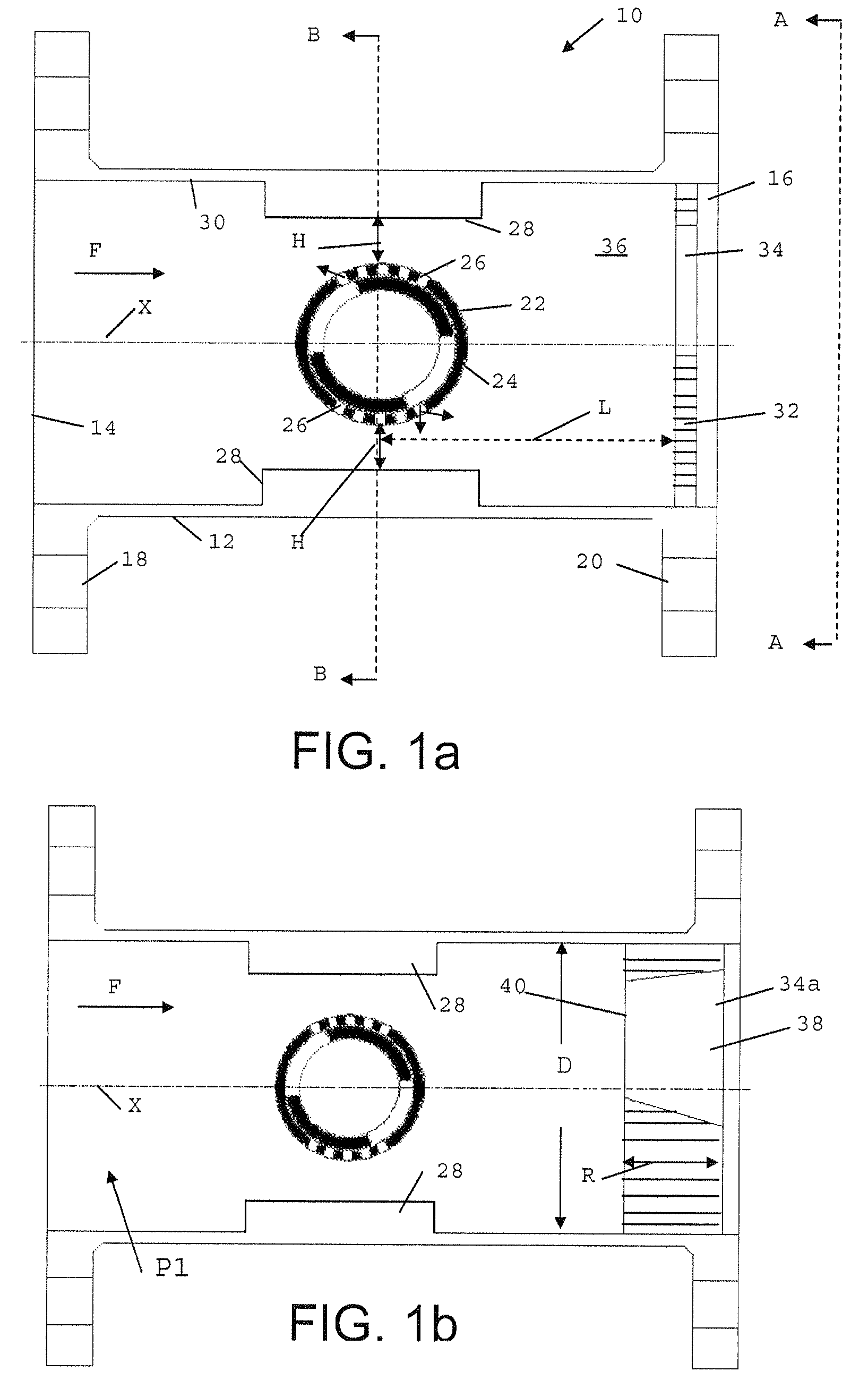
[0037]FIG. 1 illustrates a mixing apparatus 10 which comprises a tubular body 12 that defines a space forming a flow channel for the suspension in the mixing apparatus. It has a suspension inlet 14 and a suspension outlet 16 with flanges 18 and 20. The longitudinal axis of the tubular body is marked with X. The suspension flows essentially in the direction of the axis X. The mixing apparatus 10 is attached at its flange 18 to the inlet piping for incoming fiber suspension and at its flange 20 to the discharge piping for fiber suspension exiting the mixer (not shown).

[0038]The tubular body 12 is provided with a tubular feed member 22 that extends into the flow channel transversely against the longitudinal axis X of the tubular body and also against the flow direction F of the suspension. The feed member has a cylindrical wall 24 with through openings 26 for leading a substance from the member into the suspension flow channel. Openings 26 in an adequate number are provided in both the...


PUM


Abstract

The invention relates to an apparatus for mixing a gaseous or liquid substance into fiber suspension. The apparatus includes a tubular body, which defines a space that forms a flow channel for the suspension, in which body an inlet and an outlet for the suspension are arranged so that the suspension flows through the flow channel mainly in the axial direction. Further the apparatus comprises a feed member that extends into the flow channel transversely against the flow direction of the suspension and has a cylindrical wall provided with openings for leading the substance from the feed member into the flow channel. At least one protrusion is arranged on the inner surface of the tubular body in the region the feed member. A throttling member is arranged in the flow channel downstream of the feed member in the flow direction of the suspension, and a mixing chamber is formed in the flow channel between the feed member and the throttling member.

Description

RELATED APPLICATION[0001]This application is the U.S. national phase of International Application No. PCT / FI2011 / 050098 filed 4 Feb. 2011 which designated the U.S. and claims priority to Finnish Application No. 20105108 filed 4 Feb. 2010, the entire contents of each of which are hereby incorporated by reference.BACKGROUND[0002]The present invention relates to an apparatus for mixing both liquid and gaseous substances, such as chemicals, into a medium formed of solid and liquid substance, especially to fiber suspensions being generated during processing of wood or other vegetable-originating substance. To this kind of suspensions typically belong the fiber suspensions of the pulp and paper industry, such as chemical pulp and mechanical pulp suspensions, as well as pulp suspensions of paper production.[0003]For mixing chemicals and gases into fiber suspensions, dynamic mixers are used, which typically are provided with a rotating rotor for effecting the mixing, and static mixers. In t...

Claims


Application Information

Patent Timeline
IPC IPC(8): D21F1/00
CPCB01F5/0682B01F15/0201B01F5/0646B01F5/0463D21F1/00B01F5/0688B01F15/0261B01F5/0652B01F5/0451B01F25/31331B01F25/3131B01F25/433B01F25/4335B01F25/45B01F25/4521B01F35/718051B01F35/71
Inventor PELTONEN, KARILAUKKANEN, ARTOPERTTULA, TIMOVEHMAA, JANNE
Owner ANDRIZ OY
Why Eureka
Try Eureka