
Temperature controlled/limiting heating element for an electric cooking appliance

a technology of heating element and cooking element, which is applied in the direction of heating fuel, hot plate heating arrangement, lighting and heating apparatus, etc., can solve the problems of still occurring kitchen fires, reduce the risk of fire, speed up the cooking process, and quickly heat the pot and contents.

Active Publication Date: 2014-05-13
ROYNAT CAPITAL
View PDF20 Cites 29 Cited by
  • Summary
  • Abstract
  • Description
  • Claims
  • Application Information

AI Technical Summary

Benefits of technology

The solution effectively reduces the risk of kitchen fires by maintaining a safe temperature, is inexpensive to manufacture and install, and can be retrofitted to existing stoves, enhancing safety without requiring circuit modifications or professional expertise.

Problems solved by technology

Unfortunately, despite the best efforts of fire safety educators, kitchen fires still occur due to negligence, ignorance, lack of attention or forgetfulness.

Method used


Image

  • Temperature controlled/limiting heating element for an electric cooking appliance
  • Temperature controlled/limiting heating element for an electric cooking appliance
  • Temperature controlled/limiting heating element for an electric cooking appliance

Examples


Embodiment Construction

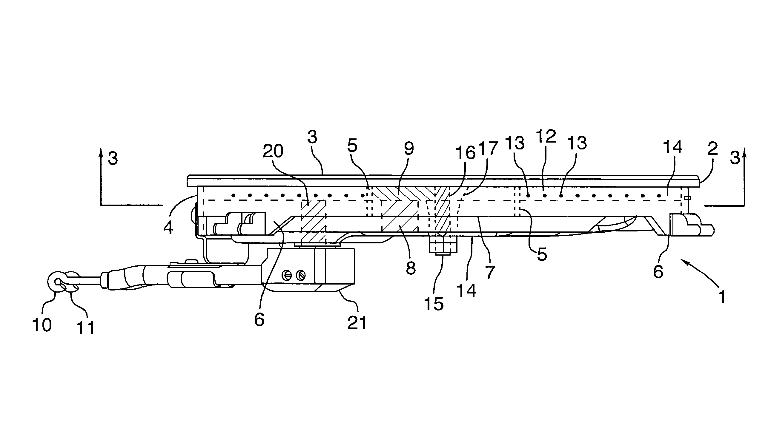
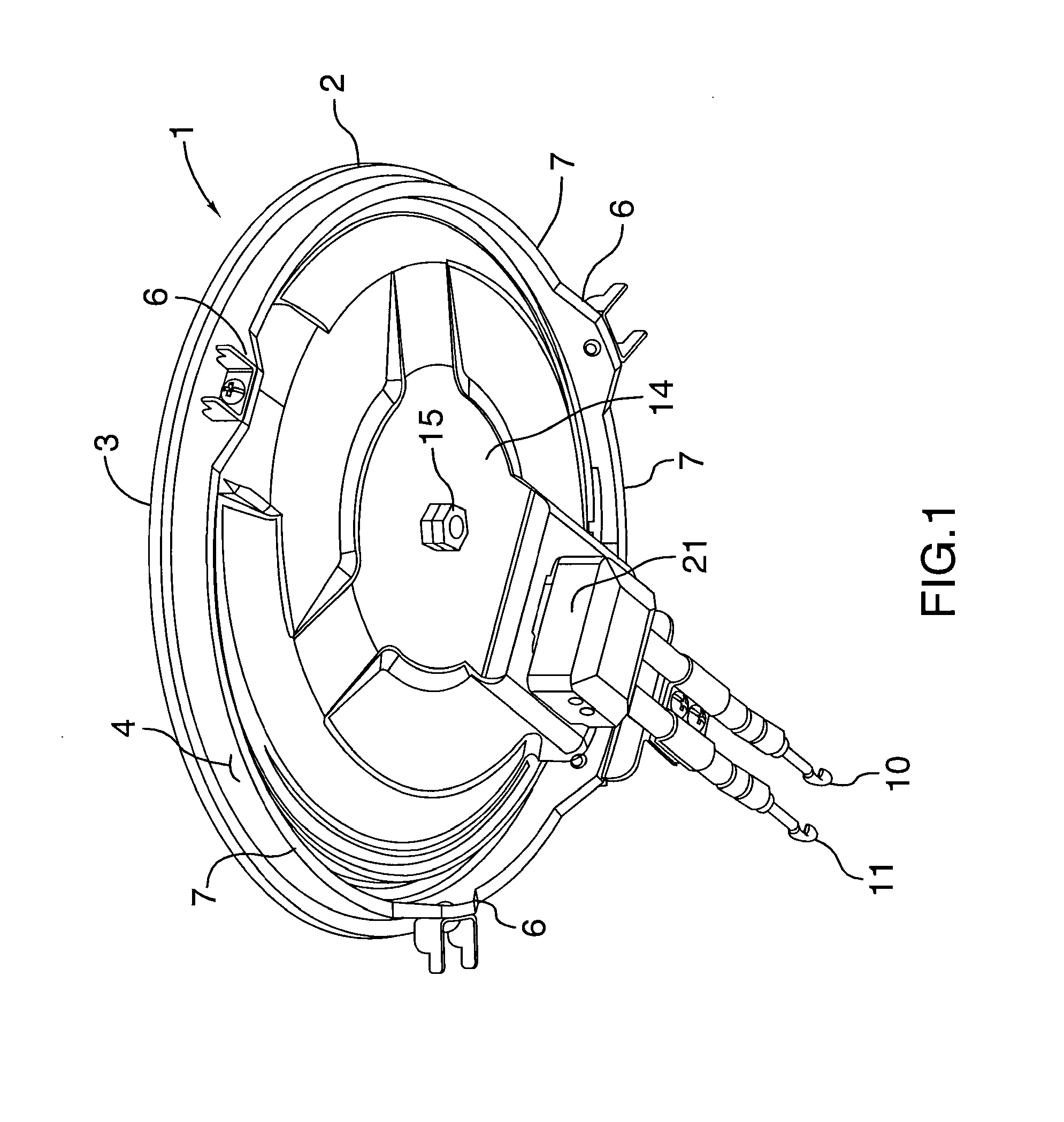
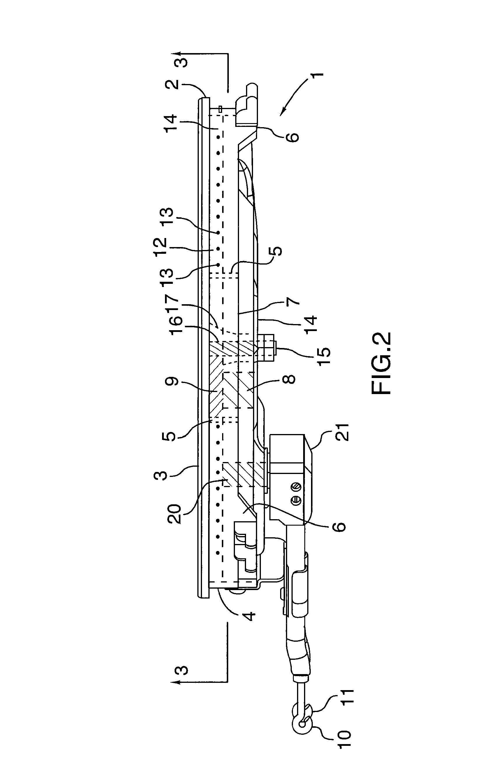
[0019]FIG. 1 shows the underside of a temperature controlled heating element 1 for an electrically powered cooking appliance such as an electric stove, hot plate or stove top. FIG. 2 shows a side view with internal components in ghost outline. The element 1 has a metal top plate 2 with an upper contact heating surface 3. The plate 2 serves to absorb heat from the electrical resistive heating wires and transfer heat through contact with a pot or pan that is placed on the upper contact heating surface 3.

[0020]As best seen in FIGS. 2-3, the plate 2 has an outer peripheral wall 4 and an inner wall 5. The plate 2, and walls 4-5 may be cast of metal formed from sintering a cast metal powder. The outer wall 4 has mounting tabs 6 (see FIGS. 1-2) for installing in a conventional recess of a stove. Between the mounting tabs 6 are hot air vent notches 7 to allow hot air to escape and vent from the stove.

[0021]As seen in FIGS. 2-3, the inner wall 5 of the plate 2 defines a central chamber in wh...


PUM

PropertyMeasurementUnit
temperatureaaaaaaaaaa

Abstract

A temperature controlled / limiting heating element for an electrically powered cooking appliance, having: a plate with an upper contact heating surface; a pair of heating element terminals adapted for removably engaging electrical power supply terminals of the electrically powered cooking appliance; a plurality of resistive heating wires, in thermal engagement with a lower surface of the top plate, comprising: a non-cycling resistive heating wire connected in series to the heating element terminals; and a cycling resistive heating wire connected in series to the heating element terminals via a thermostat switch in thermal engagement with a lower surface of the top plate, wherein the thermostat switch is normally closed when exposed to a sensed temperature below a set temperature and the thermostat switch opens when the sensed temperature is equal to or exceeds the set temperature.

Description

TECHNICAL FIELD[0001]The invention relates to a temperature controlled / limiting heating or cooking element for an electrically powered cooking appliance, particularly where the temperature is controlled as a fire prevention measure to be below a flash point or ignition temperature of commonly used cooking oils, grease and common household materials.BACKGROUND OF THE ART[0002]Cooking of food in residential buildings and homes is a major cause of fires and smoke damage. Of course fires cause significant numbers of preventable deaths, personal injuries as well as property damage. Any means of preventing kitchen fires will be perceived as an important safety advance by individuals, fire departments, insurance companies, health professionals and government agencies.[0003]Restaurant kitchens and large scale food preparation operations are protected by training professional kitchen staff in accident and fire prevention as well as with smoke detectors, fire suppression systems and fire exti...

Claims


Application Information

Patent Timeline
Patent Type & Authority Patents(United States)
IPC IPC(8): H05B1/02
CPCH05B1/0266H05B3/70F24C7/087
Inventor CALLAHAN, KEVINSHAH, REZAHU, YIBING
Owner ROYNAT CAPITAL
Learn More