Two-dimensional method and system enabling three-dimensional user interaction with a device

Inactive Publication Date: 2014-05-13
AQUIFI
View PDF8 Cites 83 Cited by
  • Summary
  • Abstract
  • Description
  • Claims
  • Application Information

AI Technical Summary

Benefits of technology

[0015]The present invention enables a user to interact with gestures in a natural way with image(s) displayed on the surface of a monitor whose display contents are governed by an appliance, perhaps a PC, a smart phone, a projector if the monitor is a whiteboard, etc. In some embodiments, the present invention includes the display as well as the appliance, in a single package. User interaction is not confined to touching the physical surface of the display but includes gestures that may occur within a three-dimensional hover zone spaced apart from the display surf

Problems solved by technology

Understandably the cost of the resultant system will increase with increases in the display size, i.e., the LCD layer.
Retrofitting touch sensing to an existing device LCD can be difficult, if not impossible.
Understandably these retro-reflective strips add to the overall thickness and cost of the display and bezel, and typically cannot be fitted retroactively to an existing LCD.
Note that such systems do not detect any information in a three-dimensional hovering region spaced-apart from the display screen surface, i.e., z>0. Thus any gesture(s) attempted by the user prior to actually touching the screen surface do not result in useful detection information or interaction.
Although they can provide true three-dimensional (x,y,z) data, TOF systems can be relatively expensive to implement and can require substantial operating power.
Operational overhead associated with acquiring three-dimensional data can be high for a touchscreen hovering application.
But a TOF system cannot simply provide three-dimensional data for ten points but must instead image the entire user

Method used


Image

  • Two-dimensional method and system enabling three-dimensional user interaction with a device
  • Two-dimensional method and system enabling three-dimensional user interaction with a device
  • Two-dimensional method and system enabling three-dimensional user interaction with a device

Examples


Embodiment Construction

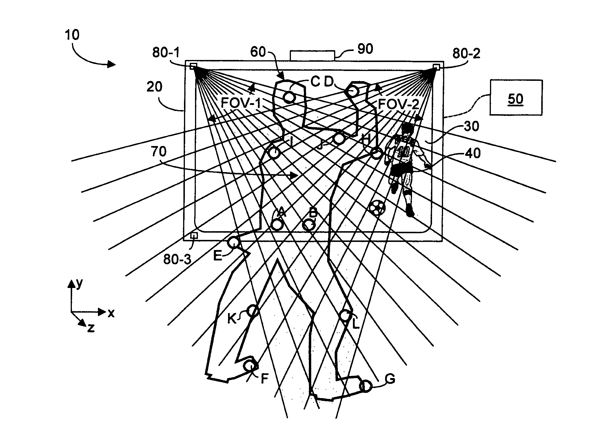
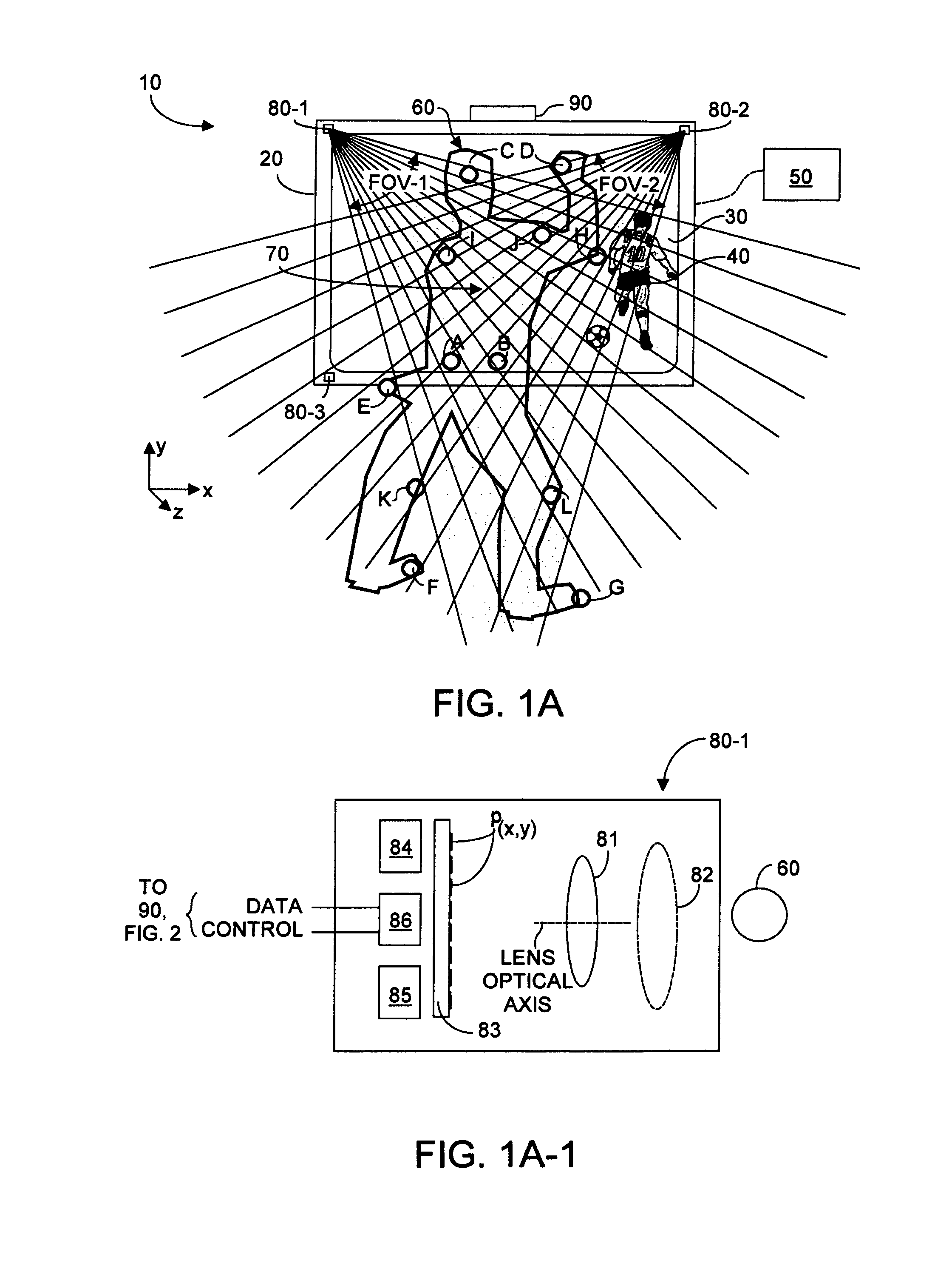
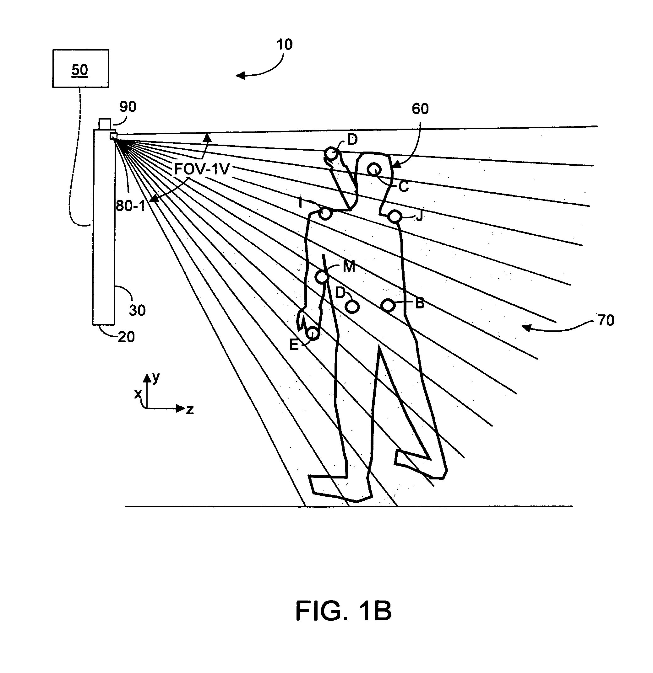
[0040]FIG. 1A is a front view of an embodiment of a system 10, according to the present invention. In overview, system 10 includes a functional grid at least two cameras 80-1, 80-2, etc. disposed relative to a monitor or display 20 so as to image in two-dimensions interaction by a user or user object 60 with imagery 40 presented on the display surface 30. As used herein the terms “user” and “user object”, will be understood to include user 60, portions of user 60, perhaps a hand, a finger, a fingertip, as well as any object held by the user used in gesturing, perhaps a passive stylus or wand. The various cameras can operate cooperatively and independently albeit substantially simultaneously, as described herein under command of an electronic unit 90. Electronic unit 90 in system 10 processes two-dimensional frames of image data captured substantially simultaneously by each camera from that camera's vantage point and provided to electronic unit 90 at a known frame rate. Software asso...


PUM


Abstract

User interaction with a display is detected using at least two cameras whose intersecting FOVs define a three-dimensional hover zone within which user interactions can be imaged. Each camera substantially simultaneously acquires from its vantage point two-dimensional images of the user within the hover zone. Separately and collectively the image data is analyzed to identify therein a relatively few landmarks definable on the user. A substantially unambiguous correspondence is established between the same landmark on each acquired image, and as to those landmarks a three-dimensional reconstruction is made in a common coordinate system. This landmark identification and position information can be converted into a command causing the display to respond appropriately to a gesture made by the user. Advantageously size of the hover zone can far exceed size of the display, making the invention usable with smart phones as well as large size entertainment TVs.

Description

RELATIONSHIP TO CO-PENDING APPLICATION[0001]This application is a continuation of applicant's U.S. provisional patent application Ser. No. 61 / 463,013, filed on 11 Feb. 2011, entitled “Systems and Methods for Implementing Natural Interfaces”.FIELD OF THE INVENTION[0002]The invention relates generally to methods and systems enabling a user to interact with an electronic device and more specifically to enabling a user to interact in a natural manner using gestures and the like with a device in three-dimensions, using two-dimensional imaging implemented with ordinary low cost devices.BACKGROUND OF THE INVENTION[0003]It is useful to enable a user to interact with the display of an electronic device by touching regions of the display, for example with a user's finger or a stylus. Existing so-called touch screens may be implemented with sensors and receptors arranged to provide a virtual (x,y) grid on the device display surface. Such mechanisms can sense where on the display user-contact w...

Claims


Application Information

Patent Timeline
IPC IPC(8): G06F3/033
CPCG06F3/017G06F3/011G06F3/033
Inventor RAFII, ABBAS
Owner AQUIFI
Why Eureka
Try Eureka