Turret assembly

a technology of remote control and weapon system, which is applied in the direction of gun mounting, protective equipment, transportation and packaging, etc., can solve the problems of reducing the number of ammunition that can be stored in the rcws, reducing the safety of combatants, so as to minimize the exposure of combatants

Active Publication Date: 2014-05-20
RAFAEL ADVANCED DEFENSE SYSTEMS
View PDF12 Cites 4 Cited by
  • Summary
  • Abstract
  • Description
  • Claims
  • Application Information

AI Technical Summary

Benefits of technology

[0014]The present invention provides a turret assembly without deck penetration for minimizing exposure of combatants to enemy forces when accessing above deck equipment, comprising a base plate on top of which is mounted at least one firable and remotely operable combatant interfaceable implement, said base plate being rotatable about a substantially vertical axis and supported for rotation by bearing means mounted within a deck of a military facility; a hatch displaceably connected to said base plate, for normally covering a hatchway formed in said base plate and for exposing said hatchway when displaced; and a rotatable disc of a slip ring unit carried by said hatch, by which electricity for operating equipment mounted on top of said deck and for initiating control signals is transmitted to said equipment.
[0028]In one aspect, the turret assembly further comprises control means for preventing the base plate from rotating when the hatch is opened.

Problems solved by technology

As the RCWS is of a limited volume and the turret assembly can support equipment only of a limited weight, including the RCWS, control equipment, communication equipment, and the ammunition, the amount of ammunition that can be stored in the RCWS is consequently also limited.
In order to access above deck equipment, such as to replenish the stock of ammunition, the combatant is endangered and dangerously exposed, for example to enemy forces, outside the confines of the vehicle and during an extended period of time.
Naturally, mechanical mechanisms for the remote feeding of weapon systems are relatively cumbersome.
As a consequence of the complexity of these ammunition feeding systems, the probability for the occurrence of malfunctions in their operation is increased.
It is also to be remembered that the presence of active mechanisms for advancing the belts of rounds or for rotating the turret basket presents a threat and safety danger to the combatants staying in the crammed compartment in the immediate proximity of the turret basket.

Method used


Image

  • Turret assembly
  • Turret assembly
  • Turret assembly

Examples


Embodiment Construction

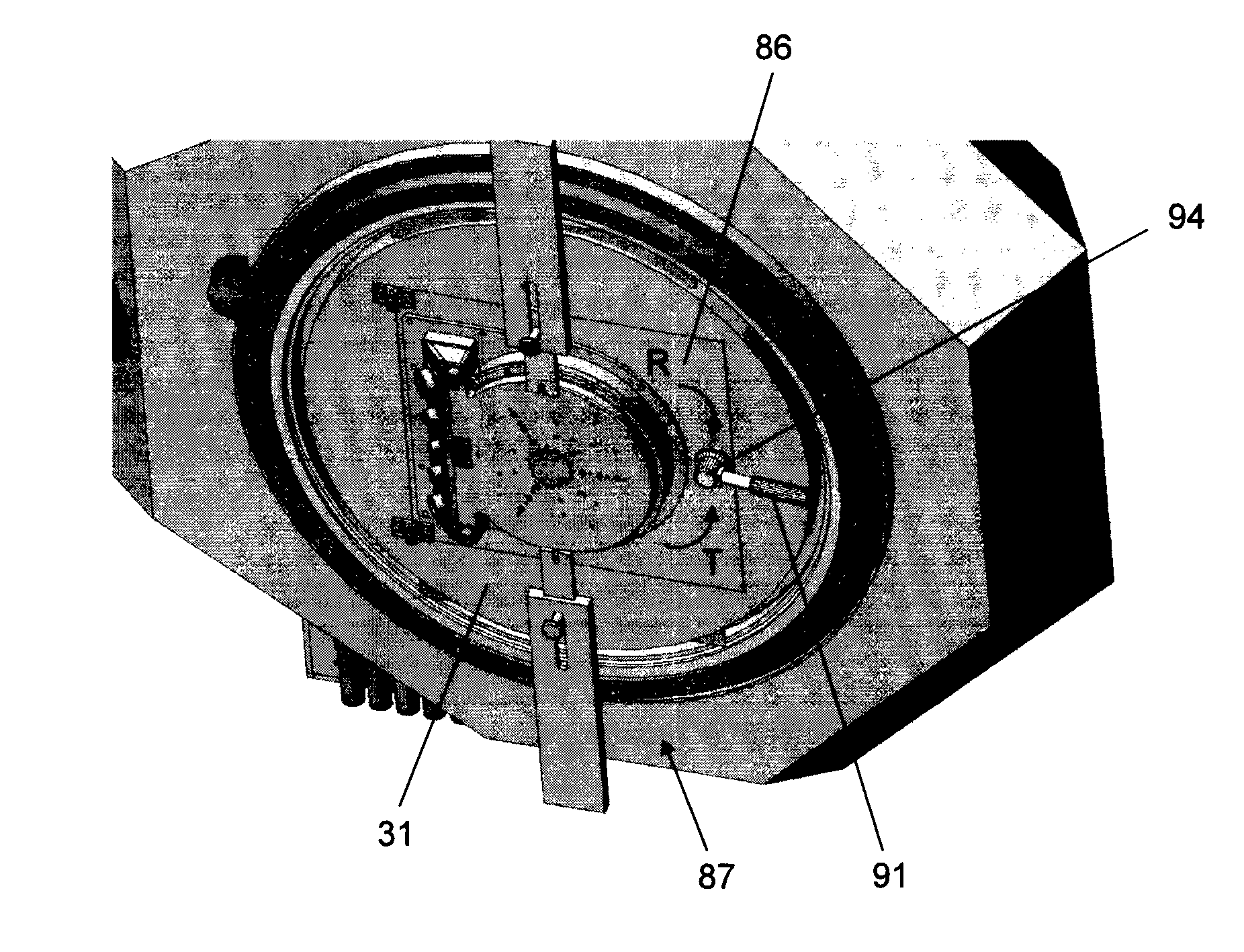
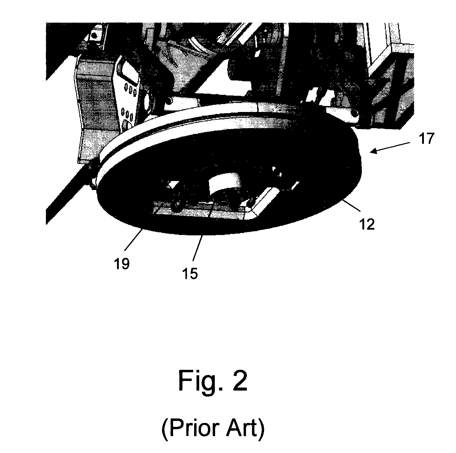
[0047]The present invention is a novel turret assembly that is provided with a displaceable hatch, on which is carried a slip ring unit. A bodily portion of a combatant is therefore able to pass through the hatchway when having to access the weapon station mounted on top of the turret assembly, obviating the need of exiting the combat vehicle in order to climb on top of the combat vehicle deck while being exposed to enemy forces.

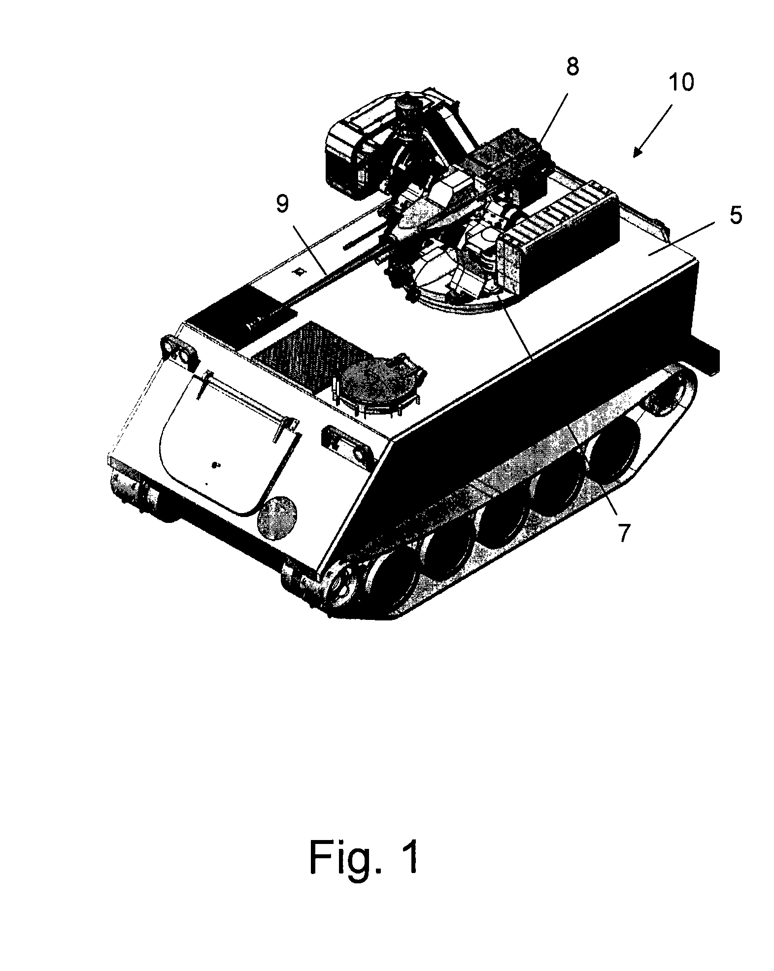
[0048]An exemplary armored combat vehicle 10 is illustrated in FIG. 1. In a central portion of deck 5 is rotatably mounted a turret assembly 7. A weapon station 8, generally comprising at least one machine gun 9, such as an anti-tank gun or an anti-aircraft gun, is mounted on turret assembly 7, and can be aimed and fired at a desired target by rotating the turret assembly, as controlled remotely by a gunner or vehicle commander located within the confines of vehicle 10 and under deck 5. Other types of equipment that may also be mounted to turret assembly 7 i...


PUM


Abstract

A turret assembly without deck penetration for minimizing exposure of combatants to enemy forces when accessing above deck equipment comprises a base plate on top of which is mounted at least one finable and remotely operable combatant interfaceable implement, the base plate being rotatable about a substantially vertical axis and supported for rotation by bearing means mounted within a deck of a military facility; a hatch displaceably connected to the base plate, for normally covering a hatchway formed in said base plate and for exposing said hatchway when displaced; and a rotatable disc of a slip ring unit carried by the hatch, by which electricity for operating equipment mounted on top of the deck and for initiating control signals is transmitted to the equipment.

Description

FIELD OF THE INVENTION[0001]The present invention relates to the field of Remote Controlled Weapon Systems or Stations (hereinafter RCWS). More particularly, the present invention relates to a turret assembly for use in conjunction with a RCWS.BACKGROUND OF THE INVENTION[0002]A RCWS is used for light and medium caliber weapons and can be installed on any type of land and sea-based vehicle. Modern military vehicles are provided with such equipment, which allow a gunner to remain in the relative protection of the vehicle. The RCWS may be installed when the vehicle is being manufactured or may be retrofitted on an existing vehicle.[0003]A typical RCWS enables a variety of devices to be operated automatically or by remote control, including 5.56 mm, 7.62 mm, and 12.7 mm machine guns, as well as 40 mm automatic grenade launchers, 30 mm cannons, anti-tank missiles, and even observation pods. Such an RCWS is designed to be mounted on, for example, light-armored, high-mobility military vehi...

Claims


Application Information

Patent Timeline
Patent Type & Authority Patents(United States)
IPC IPC(8): F41A27/20F41H5/22F41H5/20F41H7/02F41A23/24
CPCF41A27/18F41A23/24F41A27/20F41H5/20F41H7/02F41H5/223
Inventor BERKOVICH, EYALCHACHAMIAN, SHIMON
Owner RAFAEL ADVANCED DEFENSE SYSTEMS
Why Eureka
Try Eureka