Method and apparatus for performing wireline logging operations in an under-balanced well

a wireline logging and under-balanced well technology, applied in the direction of survey, borehole/well accessories, sealing/packing, etc., can solve the problems of reducing the benefits and increasing productivity value of the well, and reducing the productivity of the well. , the effect of reducing the formation damage and significant productivity loss

Inactive Publication Date: 2014-05-20
SCHLUMBERGER TECH CORP
View PDF13 Cites 30 Cited by
  • Summary
  • Abstract
  • Description
  • Claims
  • Application Information

AI Technical Summary

Benefits of technology

[0018]This method can further provide for the step of testing the logging tool prior to lowering on the drill pipe to a position adjacent the closed pressure isolation valve.
[0020]The logging string in the present invention can be made up of any number of logging and well control devices which are currently not utilized in horizontal underbalanced wells and have no alternate available in LWD (logging while drilling); such as a Formation Micro-imager (FMI); an oil base mud micro imager (OBMI); an ultrasonic borehole imager (UBI); a Reservoir Saturation Tool (RST); a Flow Scan Imager (FSI) incorporating sensors such as pressure, temperature, fluid density, flow rate, water flow logs; a Modular Dynamics Tester (MDT); a Nuclear Magnetic Resonance (NMR) Scanner; a Sonic Scanner; a Resistivity Scanner; a side-wall coring tool (MSCT); or an elemental capture spectroscope (ECS). Using the present invention TLC in an underbalanced horizontal well for standard as well as advanced technologies logging can be readily accomplished.
[0021]The apparatus of the present invention is best suited for an arrangement where the drill pipe joints between the downhole wet connector head and the cable side entry sub are substantially equivalent in length to the formation to be logged, thus permitting the full reach of the logging string to be pushed to the logging depth required. Moving the tubing string deeper into the well exposes the wireline to the open well bore formation which can crush or damage the wireline.
[0023]This invention is accomplished using a rotating blow out preventer providing a rotating rubber seal permitting rotation of a drill string under pressure while creating a sealed tubular connection; a wireline entry guide connected to the sealed side of the rotating blow out preventer; and, a wireline pressure control device connected to the wireline entry guide. The wireline entry guide can be hardfaced to limit the wear on the rotating blow out preventer from the movement of the wireline through the body. Moreover, the wireline entry apparatus can be fabricated wherein the wireline entry guide and the rotating blow out preventer comprise an integral body.

Problems solved by technology

So far as known to applicant, the problems with conveying a full suite of open hole logging tools in an under-balanced horizontal well remains unsolved.
This has forced some drilling companies and owners to insist that the well be killed between trips thus jeopardizing the benefits and increased productivity value of performing UBD.
In many cases, CT logging is considered as the only viable solution; however, this technique could be used with normal jointed pipe as a readily accessible solution not dependent on CT and its availability.
This results in damaging the virgin reservoir rock and thereby reducing the productivity of the well.
Under-balanced drilling is especially suited for horizontal wells because formation damage in horizontal over-balanced wells can be very significant due to the long contact length and contact time between reservoir rocks and drilling fluids as well as constant scraping of filter cake by the drill pipe lying down on the low side of the horizontal.
Therefore, significant productivity is lost due to formation damage in horizontal wells.
In wells where N2 injection is made to achieve under-balance, the accuracy of such productivity data is questionable due to the lack of measurements available along the entire length of drill pipe and fluctuations in the fluid density as well as flow contributions and pressures in the entire length of the open hole section.
The accuracy of such models to determine the four-phase fluid behaviors and flow characteristics in a complex well trajectory is also very limited.
Hence, productivity information obtained from under-balanced wells while drilling has a large margin of error; however, any information assists the operators determination, albeit with low accuracy, of the ultimate true potential of a well with no damage to the well.
However, in horizontal wells, the standard TLC technique as used in over-balanced drilling environment suffers from a serious limitation as a certain cable section must be kept outside of the drill pipe in length equal to the interval being logged, located between rig floor and down hole cable side entry sub which cannot be sealed around as the annular BOPs are not designed to seal around a pipe with a wire outside it and any attempt to do so could damage the cable and jeopardize the whole operation.
This means that advanced services logging operations such as high resolution imaging, production logging measurements such as downhole flow rates, phase hold ups and zonal contributions from reservoir and others not available using LWD or memory option cannot be performed with standard surface set up which is a serious disadvantage for the exploration and production (E&P) operator.
In some cases coil tubing with electric cable could be an option however the ability of coil tubing to push a heavy suite of open hole logging tools all the way to TD in a long horizontal open hole is a serious short coming, not to mention the added complexity, risk and investment needed to carry out such an operation.
Without wireline log data, it is not possible for the E&P operators to accurately determine the ultimate true productivity potential of the well.
It is also not possible to optimize completion design based on accurate productivity profiles.
It is also not possible to improve the accuracy of while drilling productivity measurements.

Method used


Image

  • Method and apparatus for performing wireline logging operations in an under-balanced well
  • Method and apparatus for performing wireline logging operations in an under-balanced well
  • Method and apparatus for performing wireline logging operations in an under-balanced well

Examples


Embodiment Construction

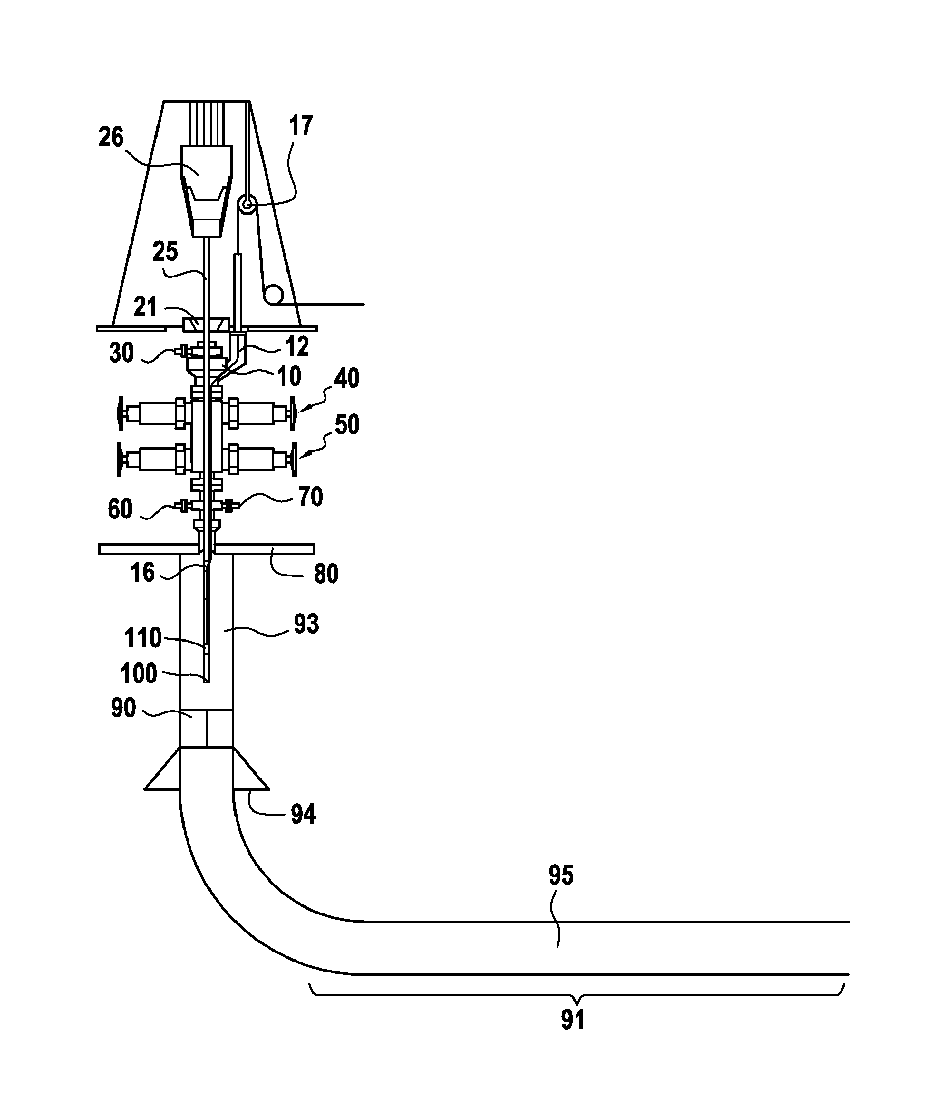
[0037]The logging of deviated or horizontal wells using a drill string to set the logging tool string in place has been more fully described in U.S. Pat. No. 5,871,052, the contents of which are fully incorporated herein by reference as if copied herein verbatim. In the present inventive method, the logging tool string must be rigged up and lowered into the well bore while maintaining the underbalanced well bore at its underbalanced pressure but without killing the well by pumping in a mud column to contain the downhole pressure.

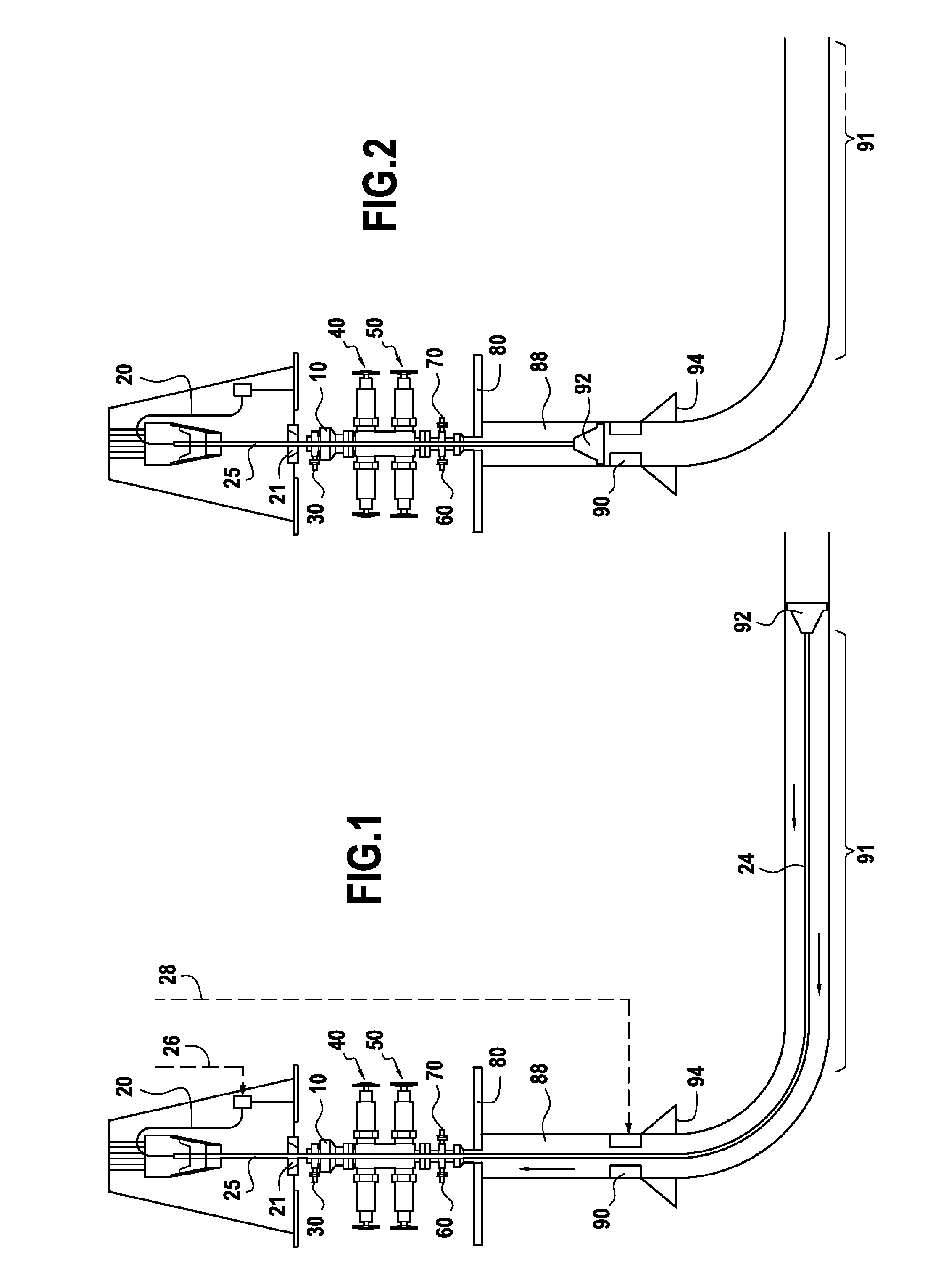
[0038]As can be readily seen in FIG. 1, the principal issues for underbalanced drilling (UBD) is the maintenance of pressure at the surface while controlling the well from kicking or blowing out. Accordingly, the safety needs at the surface must be counterbalanced with the need to maintain only so much pressure on the well bore as is required to avoid contain the natural pore pressure within the well bore. Pressure is managed by an annular rotary blow-out pr...


PUM


Abstract

A method and an apparatus log an underbalanced open hole well without killing the well or causing formation damage to maintain well control during the process. The installation of the well logging equipment is accomplished while holding the underbalanced open hole at its optimal pressure, then conveying the logging string on a drill string into the open hole portion to total depth and logging while removing the logging string from the total depth to be logged with a cable side entry sub. The invention also provides a unique configuration of equipment to accomplish the logging using what is normally referred to as tough logging condition techniques.

Description

INTRODUCTION[0001]The invention relates to a well-logging technique and apparatus for accomplishing such logging without killing the well which has been horizontally drilled using under-balanced drilling techniques; more specifically, a process and apparatus for rigging up and completing wireline logging operations in a horizontal well which has been drilled using under-balanced drilling technique without killing the well by selectively introducing logging tools into an under-balanced well bore.BACKGROUND OF INVENTION[0002]Different techniques are being developed to circumvent the problem of sealing around the pipe and wireline cable for example, logging while drilling (LWD), memory shuttles conveyed by pumping them down inside pipe or using slim tools such as RST conveyed with cable inside drill pipe. So far as known to applicant, the problems with conveying a full suite of open hole logging tools in an under-balanced horizontal well remains unsolved.[0003]Key benefits to pursue UB...

Claims


Application Information

Patent Timeline
Patent Type & Authority Patents(United States)
IPC IPC(8): E21B47/12E21B19/08E21B34/02
CPCE21B47/12E21B2021/006E21B33/072E21B17/025E21B33/085E21B21/085
Inventor KHAN, WAQAR
Owner SCHLUMBERGER TECH CORP
Why Eureka
Try Eureka