Method and apparatus for motional/vibrational energy harvesting via electromagnetic induction
What is AI technical title?
AI technical title is built by Patsnap AI team. It summarizes the technical point description of the patent document.
a technology of electromagnetic induction and motion, which is applied in mechanical energy handling, nuclear power plants, nuclear engineering, etc., can solve the problems of low power output of these miniaturized devices, inability to power many practical devices, and inability to meet the needs of small-scale devices,
Active Publication Date: 2014-05-20
UNIV OF FLORIDA RES FOUNDATION INC
View PDF24 Cites 30 Cited by
Summary
Abstract
Description
Claims
Application Information
AI Technical Summary
This helps you quickly interpret patents by identifying the three key elements:
Problems solved by technology
Method used
Benefits of technology
Problems solved by technology
For example, micromachining and micro-electro-mechanical system (MEMS) technologies have been used to produce sub-millimeter microchip-sized devices, but the power output from these miniaturized devices has been very low (often nW-μW level), which appears to be too small to power many practical devices.
This narrowband frequency response is especially problematic for micromachined devices, which typically possess resonant frequencies in excess of 1 kHz, well above the frequency range of mechanically- or human-induced vibrations (1-500 Hz).
Additionally, most current systems only respond to one axial direction of motion.
Moreover, prototypes have successfully demonstrated electrical power extraction, but conversion and regulation of the extracted electrical power to the appropriate voltage / current levels for compatibility with electronic devices continues to present engineering challenges.
Conventional power electronic circuit approaches currently do not appear to function efficiently at the low voltages and currents supplied by a typical vibrational energy harvester.
Method used
Image
Click on the blue label to locate the original text in one second.
Reading with bidirectional positioning of images and text.
Examples
example 1
[0069]A specific embodiment of the invention is directed to a method and apparatus incorporating a non-resonant, vibrational energy harvester architecture intended for human-motion energy scavenging. The design utilizes a unidirectionally-magnetized (NdFeB) permanent magnet ball that rolls and translates inside a spherical housing when subjected to motion, such as human motion. The sphere containing the magnetic ball is wrapped with one or more copper coils. When the ball moves, these coils are exposed to a time-varying magnetic flux and generate a voltage. The ball positioned with the spherical housing can move under a large range of non-specific motions.
[0070]Two different spherical device architectures were investigated in this example, as shown in FIGS. 13A and 13B. The first design incorporates a single coil wrapped around the equator of the spherical cage containing the permanent magnet ball. The second design utilizes two series-connected, counter-wound coils that were offset...
PUM
Property
Measurement
Unit
diameter
aaaaa
aaaaa
diameter
aaaaa
aaaaa
diameter
aaaaa
aaaaa
Abstract
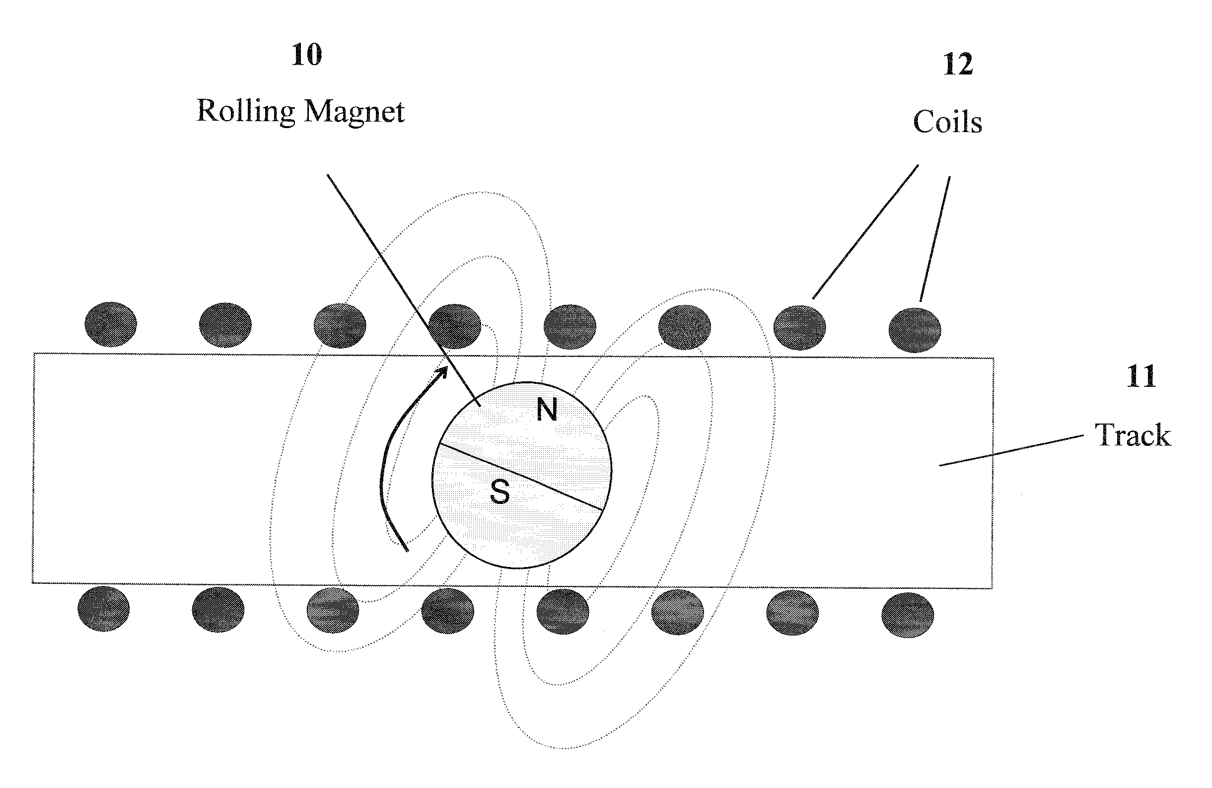
A method and apparatus for motional / vibrational energy harvesting are disclosed. Embodiments of the subject invention utilize the non-resonant chaotic behavior of a free-rolling magnet to generate power. In one embodiment, the magnet can be spherical, cylindrical, or elliptical. The magnet can roll about a linear, cylindrical, helical, or cage-like track. The changing magnetic flux due to the magnet rolling about the track induces current in surrounding coils. The coils can be provided around the track using a continuous winding placement, segmented winding placement, or fractional winding placement. Multiple coil phases are also possible. For embodiments utilizing multiple magnets, spacers can be used to maintain a separation between magnets.
Description
CROSS-REFERENCE TO RELATED APPLICATIONS[0001]This application is a continuation-in-part of International Patent Application No. PCT / US2009 / 032867, filed Feb. 2, 2009, which claims the benefit of U.S. Provisional Application Ser. No. 61 / 025,698, filed Feb. 1, 2008, and this application claims the benefit of U.S. Provisional Application Ser. No. 61 / 286,603, filed Dec. 15, 2009, the disclosures of which are hereby incorporated by reference in their entireties, including any figures, tables, or drawings.BACKGROUND OF INVENTION[0002]Long lasting, high power density power sources are important to enable emerging technologies such as wireless sensor networks, robotic platforms, and electronic devices for consumer, military, medical, aerospace and other applications. To meet the energy demands for these applications, devices that scavenge power from the environment (e.g., solar, thermal, vibrations) are of great practical interest. Various energy harvesting and scavenging methods exist for ...
Claims
Application Information
Patent Timeline
Application Date:The date an application was filed.
Publication Date:The date a patent or application was officially published.
First Publication Date:The earliest publication date of a patent with the same application number.
Issue Date:Publication date of the patent grant document.
PCT Entry Date:The Entry date of PCT National Phase.
Estimated Expiry Date:The statutory expiry date of a patent right according to the Patent Law, and it is the longest term of protection that the patent right can achieve without the termination of the patent right due to other reasons(Term extension factor has been taken into account ).
Invalid Date:Actual expiry date is based on effective date or publication date of legal transaction data of invalid patent.

