Method for monitoring fugitive gas emissions from the soil, via vertical concentration measurements

a technology of concentration measurement and soil, applied in the field of atmospheric pollution detection and control, can solve the problems of inability to provide the actual localization of the source of emission, the positioning of such back-reflectors is quite expensive and difficult on vast surfaces, and the application is limited to a large area

Active Publication Date: 2014-05-20
TEA SISTEMI
View PDF12 Cites 25 Cited by
  • Summary
  • Abstract
  • Description
  • Claims
  • Application Information

AI Technical Summary

Benefits of technology

[0016]Subject of the present invention is to provide a method for monitoring a possible leakage of a gas such as, for example, methane or CO2, particularly from area sources that is reliable and simultaneously simple to carry out.
[0020]According to an important aspect of the present invention the proposed method, providing concentration measurements with remote detection optical instruments which do not require the use of back-reflectors has the advantage of also easily monitoring sites of irregular orography, with a high degree of accuracy and low costs. Furthermore, using an optical detection technology such as TDLAS, it allows attaining the further advantage of not requiring calibrating the measurements in advance. The specific use of aircrafts allows the environmental monitoring and protection also in remote sites—hazardous and inaccessible using other means—and the use of the UAV specifically presents the further advantage of avoiding involving personnel potentially exposed to health risks.
[0023]In particular the methodology provides for the definition of an ideal plane arranged downwind and perpendicular thereto, having a width sufficient to contain the projection of the site to be monitored and placed at a distance from the site such to contain, at the aircraft sampling height, the whole gaseous effluent released from the site. The aircraft, bearing the remote detection optical instrument, overflying the site to be mapped at a height within the aforementioned ideal plane, provides discrete vertical measurements of fugitive gas concentration mediated on the height. According to such measurements the pollutant flow can be evaluated. The method according to the invention has the advantage to allow the identification and quantification of the fugitive gases flows in relatively wide sites (of the order of thousands of square meters) with a limited number of concentration measurements.

Problems solved by technology

However, though rigorous, even at very low ranges of concentrations, these measurements apply in an extremely effective manner to small sites and, given the accurateness of the measurement, they may have limitations for applications to vast areas.
In addition this system requires the use of back-reflectors on the axes of the beams along which the energy is emitted, the positioning of such back-reflectors being quite expensive and difficult on vast surfaces.
Furthermore the mapping thus obtained solely regards the concentrations of pollutants, without considering the meteorological conditions present in the area of interest and does not give any indication regarding the flows.
Though providing the mapping in terms of concentration of natural gas in the area of interest in real time, the method disclosed in the aforementioned patent is not capable of providing the actual localization of the source of emission because it does not consider the wind fields present in the area.
The methodology of inversion of the dispersion models allows to identify and quantify the source flow in the site, but it is onerous in terms of required scans, especially for relatively wide sites, besides being a little accurate and requiring a huge computational effort.
Regardless of the high degree of sensitivity of the instruments used, the aforementioned systems are limited to measuring the concentration data without considering the meteorological data: furthermore the use of such instruments, in combination with aerial means, requires quite high investment and management costs.
Requiring the use of aircrafts, this invention reveals the drawback of being quite expensive and the use of back-reflectors makes the use of the apparatus difficult to manage.

Method used


Image

  • Method for monitoring fugitive gas emissions from the soil, via vertical concentration measurements
  • Method for monitoring fugitive gas emissions from the soil, via vertical concentration measurements
  • Method for monitoring fugitive gas emissions from the soil, via vertical concentration measurements

Examples


Embodiment Construction

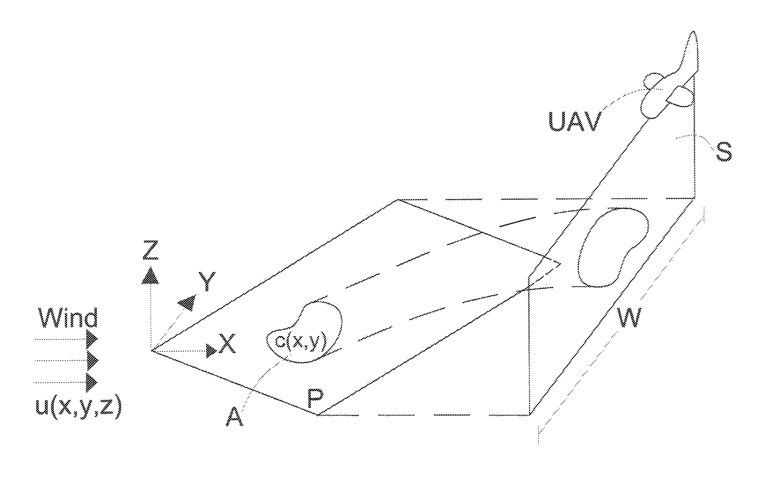
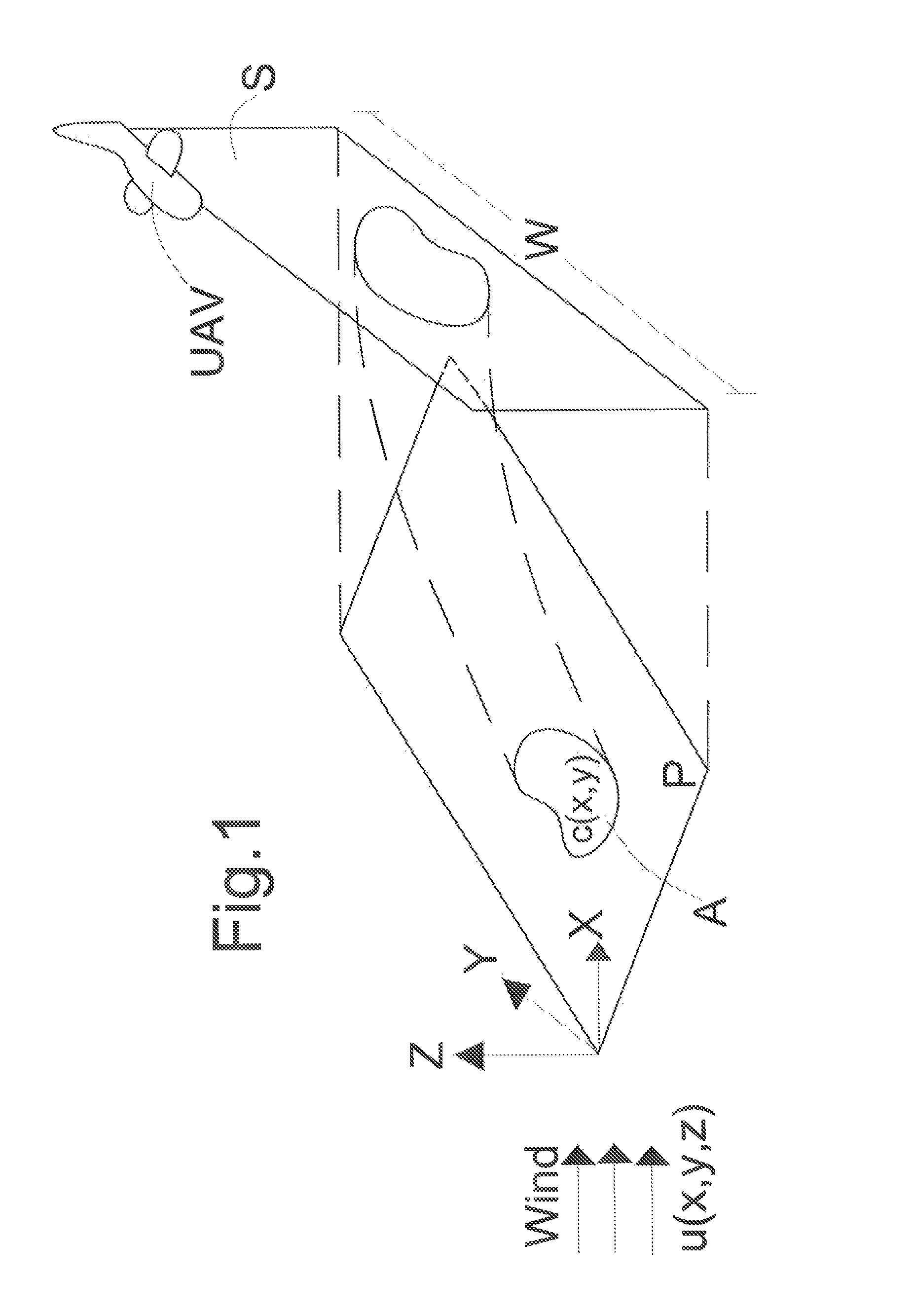
[0028]With reference to FIG. 1, the site of a generic dispersed source, assimilated to a plane surface of coordinates (x,y) is indicated with P. Assuming the point flow q(x,y) constant during the measurement and indicated with A the area corresponding to the extent of the source of fugitive gas, said area being contained in the site to be monitored P, the total fugitive gas flow is described by the following equation:

[0029]Q=∫A⁢q⁡(x0,y)⁢⁢ⅆA(1)

[0030]The equation (1) in the case of uniform area source q0 in the area A is simplified as follows:

Q=qnA  (2)

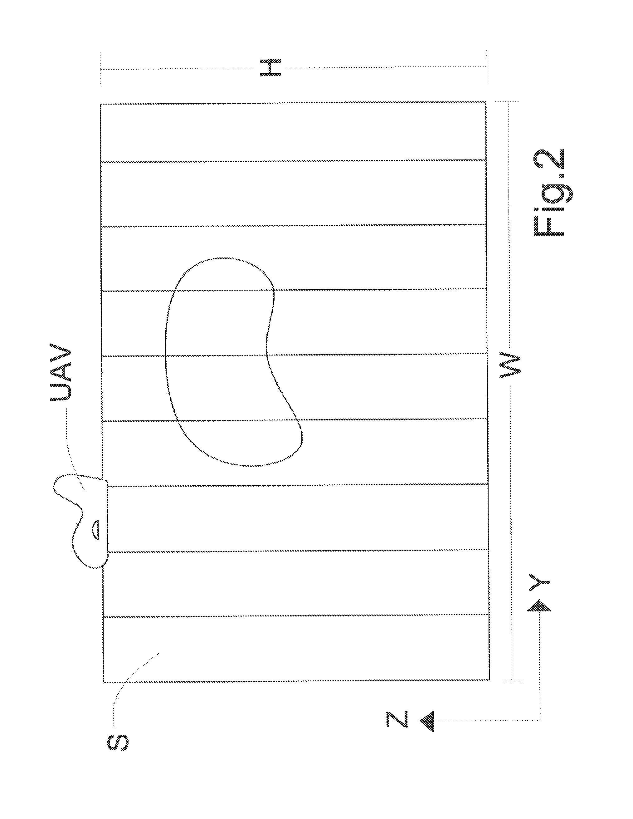
[0031]The wind direction is that of the axis x and x0 is the distance at which a vertical sampling plane S is pieced with respect to the point of the site P impacted—as the first—by the wind. The sampling plane S has a width W such as to contain the projection of the site to be monitored P. Once the generic wind field is indicated with u(x,y,z), the wind field present on S is indicated with u(x0,y,z). Using meteorological stations place...


PUM

PropertyMeasurementUnit
altitudeaaaaaaaaaa
widthaaaaaaaaaa
heightaaaaaaaaaa

Abstract

Method for the quantification of the fugitive gas flow from a dispersed source (A) by monitoring with a remote detection optical instrument mounted on an aircraft (UAV) which moves at a determined height along a plane (S) perpendicular to the direction of the wind field (u), such wind field being known through suitable positioning of meteorological stations within and in areas neighboring the site to be monitored according to known techniques and use of commercially available diagnostic meteorological models. By this instrument discrete vertical measurements are carried out of the fugitive gas concentration averaged over said height along the whole width (W) of the plane (S) to yield corresponding mean vertical concentration values and, according to mean wind speed values detected at said discrete vertical measurements, a value of the fugitive gas flow (Q) is obtained by integrating the product of the mean vertical concentration values and of the corresponding mean wind speed values with respect to the surface of the sampling plane (S). The obtained value of the fugitive gas flow (Q) is corrected by a corrective factor (a) obtainable by comparing concentration values obtained by direct measurements and values calculated by dispersion models.

Description

CROSS-REFERENCE TO RELATED APPLICATION[0001]This application is a 371 of PCT / IB2011 / 054351, filed Oct. 4, 2011, which in turn claims the benefit of priority from Italian Patent Application Serial No. FI2010A000208, filed Oct. 6, 2010, the contents of each of which are incorporated herein by reference.FIELD OF THE INVENTION[0002]The present invention refers to the field of the detection and control of sources of atmospheric pollution and more precisely it regards the mapping of gaseous emissions especially by using unmanned aerial vehicles, (UAVs), by using remote detection techniques. More in particular the invention refers to a method for the detection of emissions from the soil of potentially hazardous gaseous substances dispersed in the air such as, but not limited to, methane or carbon dioxide, in terms of total gas flow emitted and characterization and localisation of the source of emission. The present invention is particularly, but not exclusively, suitable for monitoring sit...

Claims


Application Information

Patent Timeline
Patent Type & Authority Patents(United States)
IPC IPC(8): G01N21/00
CPCG01N2021/1795G01N2021/399G01N21/3103G01M3/38G01N2201/0214G01N21/3504
Inventor ANDREUSSI, PAOLO
Owner TEA SISTEMI
Why Eureka
Try Eureka