Power transmission system of crank structure

a technology of power transmission system and crank structure, which is applied in the direction of crankshafts, machines/engines, gearing, etc., to achieve the effect of increasing acceleration force and hill climbing ability, large maximum torque, and increasing maximum torqu

Inactive Publication Date: 2014-06-03
LEE YOUNG HEE
View PDF8 Cites 1 Cited by
  • Summary
  • Abstract
  • Description
  • Claims
  • Application Information

AI Technical Summary

Benefits of technology

[0008]In gasoline engines, only 25 to 30% of the energy generated by a power stroke is converted into effective power for engine power and the other energy of 70 to 75% is lost. Therefore, the present invention has been made in an effort to improve acceleration force and hill climbing ability by increasing torque that can be generated by a internal combustion engine and consequently improve effective output to the fuel consumption amount of the internal combustion engine, that is, the fuel efficiency by increasing effective power (indicated horsepower), by improving the power transmission assembly such that piston power generated by a power stroke is converted into large torque and power for compression and exhaust strokes in which the direction of power transmission changes is converted from smaller torque in the internal combustion engine.
[0010]Accordingly, while a piston is moved from the TDC to the BDC by a power stroke in the internal combustion engine, the distance from the rotation center of the elliptical gear 3 replacing the crank arm to the power transmission point 6 decreases and the distance from the rotation center 7 of the elliptical gear 4 engaging and rotating with the gear 3 to the power transmission point 6 increases, so that piston power is converted into larger toque. Further, while the piston is moved from the BDC to the TDC by an intake stroke and an exhaust stroke in the four internal combustion engine, the distance from the rotation center 5 of the elliptical gear 3 replacing the crank arm to the power transmission point 6 increases and the distance from the rotation center 7 of the elliptical gear 4 engaging and rotating with the gear 3 to the power transmission point 6 decreases, so that power for the strokes of the piston is generated from smaller torque.
[0018]Therefore, it is possible to generate larger maximum torque in an 8-cylinder internal combustion engine with an improved power transmission assembly and the acceleration force and hill climbing ability is increased, with the generation of large maximum torque. Further, it is possible to generate larger effective power (indicated horsepower) by generating larger torque from energy generated by the power stroke in a internal combustion engine and generating piston power for the compression and exhaust strokes from smaller torque to reduce the loss of power.

Problems solved by technology

Therefore, the four cycle internal combustion engines generate power for engine power during the power stroke, but consume the power generated by other pistons during the other strokes (intake, compression, and exhaust) except for the power stroke.

Method used


Image

  • Power transmission system of crank structure
  • Power transmission system of crank structure
  • Power transmission system of crank structure

Examples


Embodiment Construction

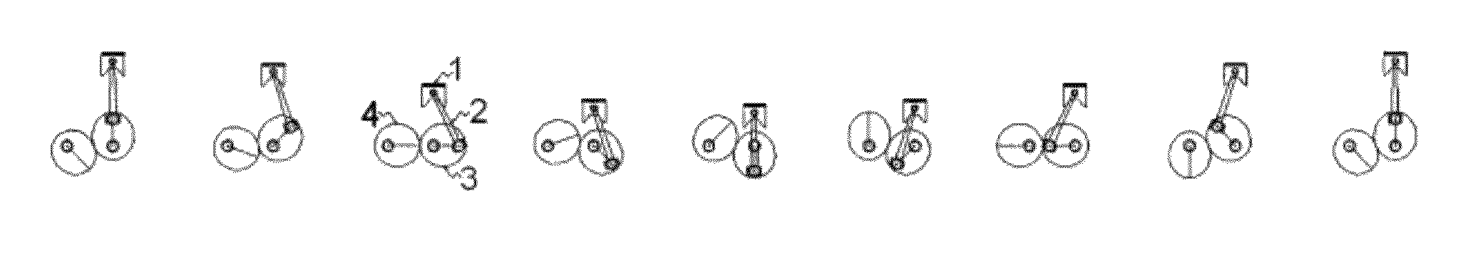
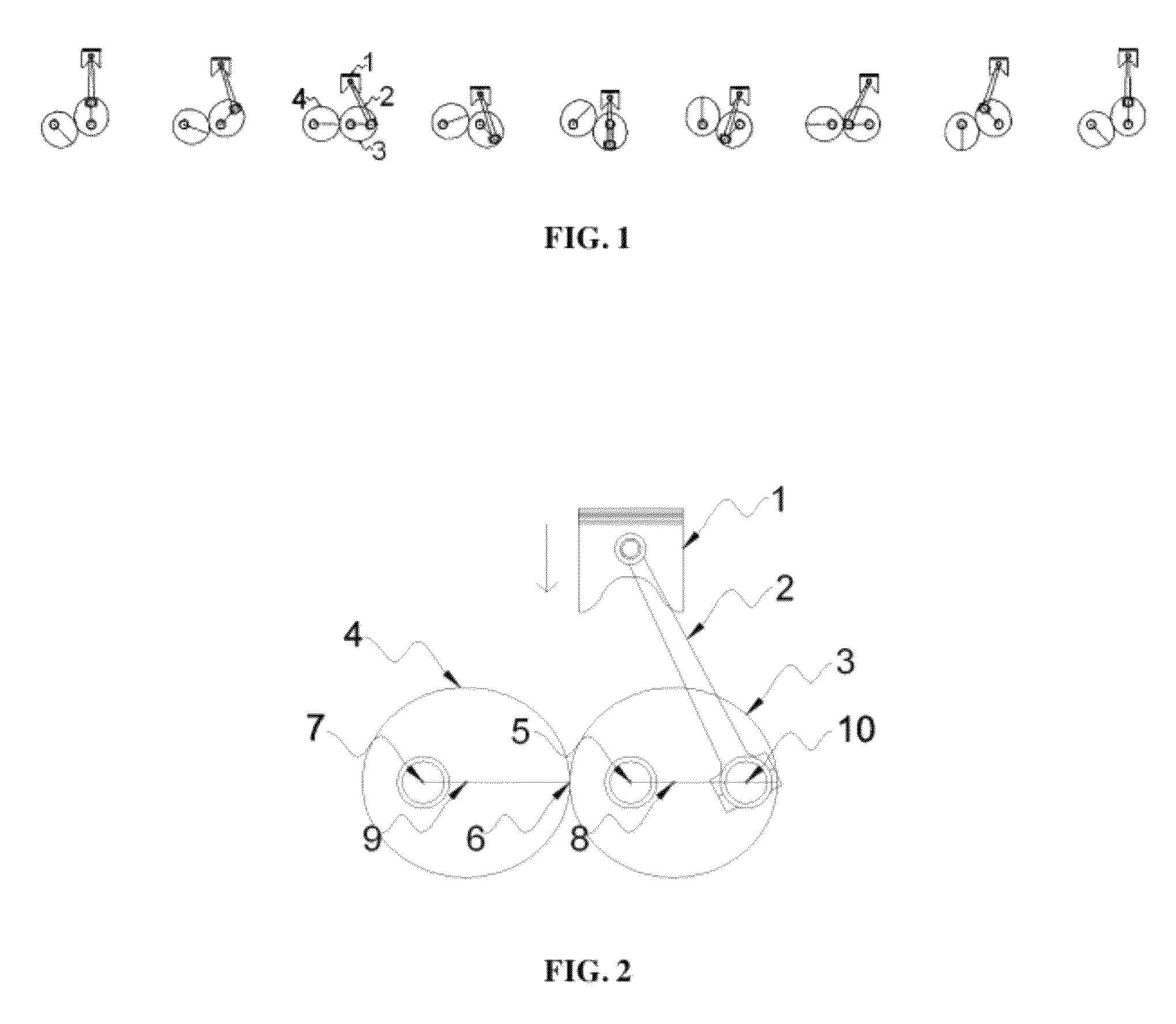
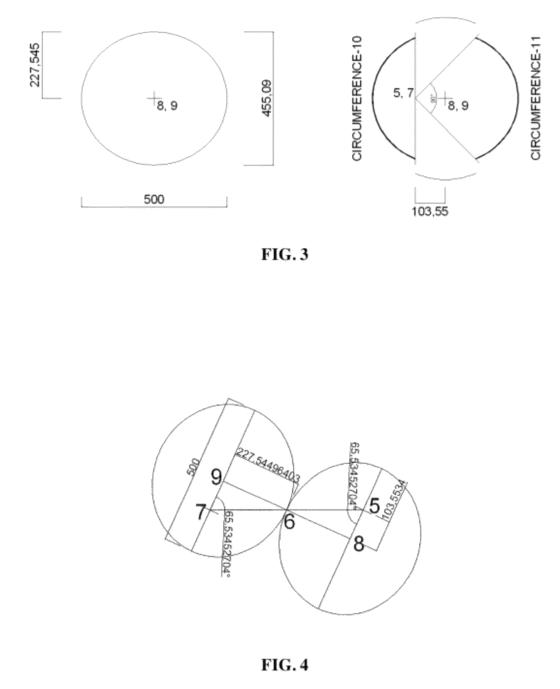
[0024]A crank arm that is coupled to a connecting rod connected to a piston of a internal combustion engine and rotates a crankshaft is replaced by an elliptical gear 3 and another elliptical gear 4 having the same size and shape is assembled to engage and rotate such that the major axes of the elliptical gears 3 and 4 are on a horizontal line when the piston is positioned at the middle point in the range of up-down motion and the shapes of the ellipses are the same, as shown in FIG. 2.

[0025]Further, the elliptical gears 3 replacing the crank arm should be rotatably fixed by separating the crankshaft for each piston such that the gears rotate at different speeds, and the other elliptical gears 4 engaging and rotating with the gear 3 should be integrally fitted on a rotary shaft to rotate at the same speed, in which torque of the rotary shaft is effective power (indicated horsepower) of the internal combustion engine.

[0026]In the power transmission assembly, the crankshaft rotates by...


PUM


Abstract

A crank arm of a internal combustion engine is replaced by an elliptical gear 3 and another elliptical gear 4 having the same size and shape is assembled to engage and rotate such that the positions moved by a predetermined distance along the major axes of ellipses from centers 8 and 9 of the ellipses become rotation centers 5 and 7 of the elliptical gears 3 and 4 to alternately change the distances from the rotation centers of the engaged elliptical gears to a power transmission point 6 in accordance with the direction of power transmission. The present invention provides a power transmission assembly for improve on fuel efficiency of a internal combustion engine that makes it possible to improve acceleration force and hill climbing ability by generating larger torque and to generate large effective power by reducing the loss of power.

Description

CROSS REFERENCE TO RELATED APPLICATION[0001]This application claims the priority of Korean Patent Application No. 10-2010-0016908, filed on Feb. 25, 2010 in the KIPO (Korean Intellectual Property Office). Further, this application is the National Phase application of International Application No. PCT / KR2011 / 000888 filed Feb. 10, 2011, which designates the United States and was filed in Korean.BACKGROUND OF THE INVENTION[0002]1. Field of the Invention[0003]The present invention relates to a power transmission assembly for improve on fuel efficiency of a internal combustion engine by improving the power transmission assembly of a internal combustion engine, which generates driving force by converting the reciprocating motion of a piston into rotating motion of a crankshaft, in order to generate larger torque in an internal combustion engine with the same displacement such that acceleration and hill climbing abilities are improved and larger effective power (indicated horsepower) is ge...

Claims


Application Information

Patent Timeline
Patent Type & Authority Patents(United States)
IPC IPC(8): F02B75/32
CPCF16C3/06F01B9/042F02B75/32Y10T74/19647
Inventor LEE, YOUNG, HEE
Owner LEE YOUNG HEE
Why Eureka
Try Eureka