
Concentrating solar power with glasshouses

a technology of solar energy and glasshouses, applied in thermal-pv hybrid energy generation, sustainable manufacturing/processing, instruments, etc., can solve the problems of requiring roughly 20 kg of structural steel for the construction, the reflectivity of the concentrator is sensitive to damage, and the glass is relatively fragile and vulnerable to hail and other forms of damag

Active Publication Date: 2014-06-10
GLASSPOINT SOLAR
View PDF40 Cites 22 Cited by
  • Summary
  • Abstract
  • Description
  • Claims
  • Application Information

AI Technical Summary

Benefits of technology

The patent text discusses the use of concentrated solar power and photovoltaic systems to improve performance and efficiency. The text describes various types of concentrated solar energy collection systems and their components, including mirrors, concentrators, and receivers. The technical effects of the patent text include improved performance, efficiency, and utility of concentrated solar power and photovoltaic systems. The text also mentions the advantages of concentrated solar energy over simpler systems that directly use incident solar energy, such as reduced cost of gathering sunlight over a given area and converted solar energy to useful energy.

Problems solved by technology

Reflectivity of a concentrator is sensitive to damage, tarnishing, and dirt buildup since only directly reflected sunlight, not scattered sunlight, is effectively focused.
Glass is relatively fragile and vulnerable to hail and other forms of damage unless it is suitably thick, e.g. 4-5 mm for relatively larger minors.
The winds add an additional 10,000 lbs of load beyond the 1000 lb weight of the mirror, resulting in complex construction requiring roughly 20 kg of structural steel for every meter of minor area in a dish system.
In some CST systems, parabolic dishes with point-focus receivers are not used, at least in part because structural demands on the dish are prohibitive and designing a tracking mechanism that keeps the focal point fixed (to avoid complex and expensive mechanisms to connect the thermal medium system) is impractical.

Method used


Image

  • Concentrating solar power with glasshouses
  • Concentrating solar power with glasshouses
  • Concentrating solar power with glasshouses

Examples


selected embodiment details

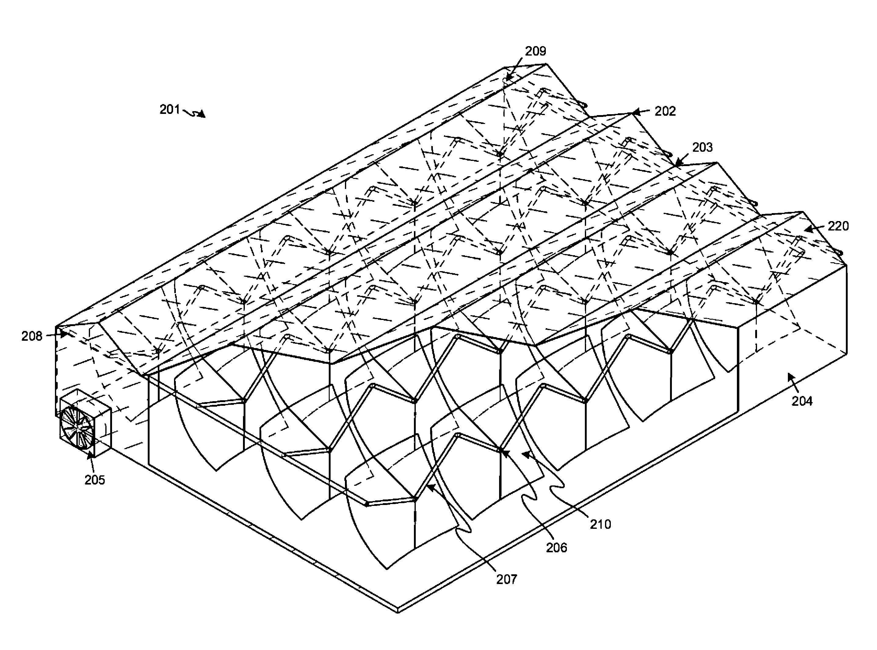
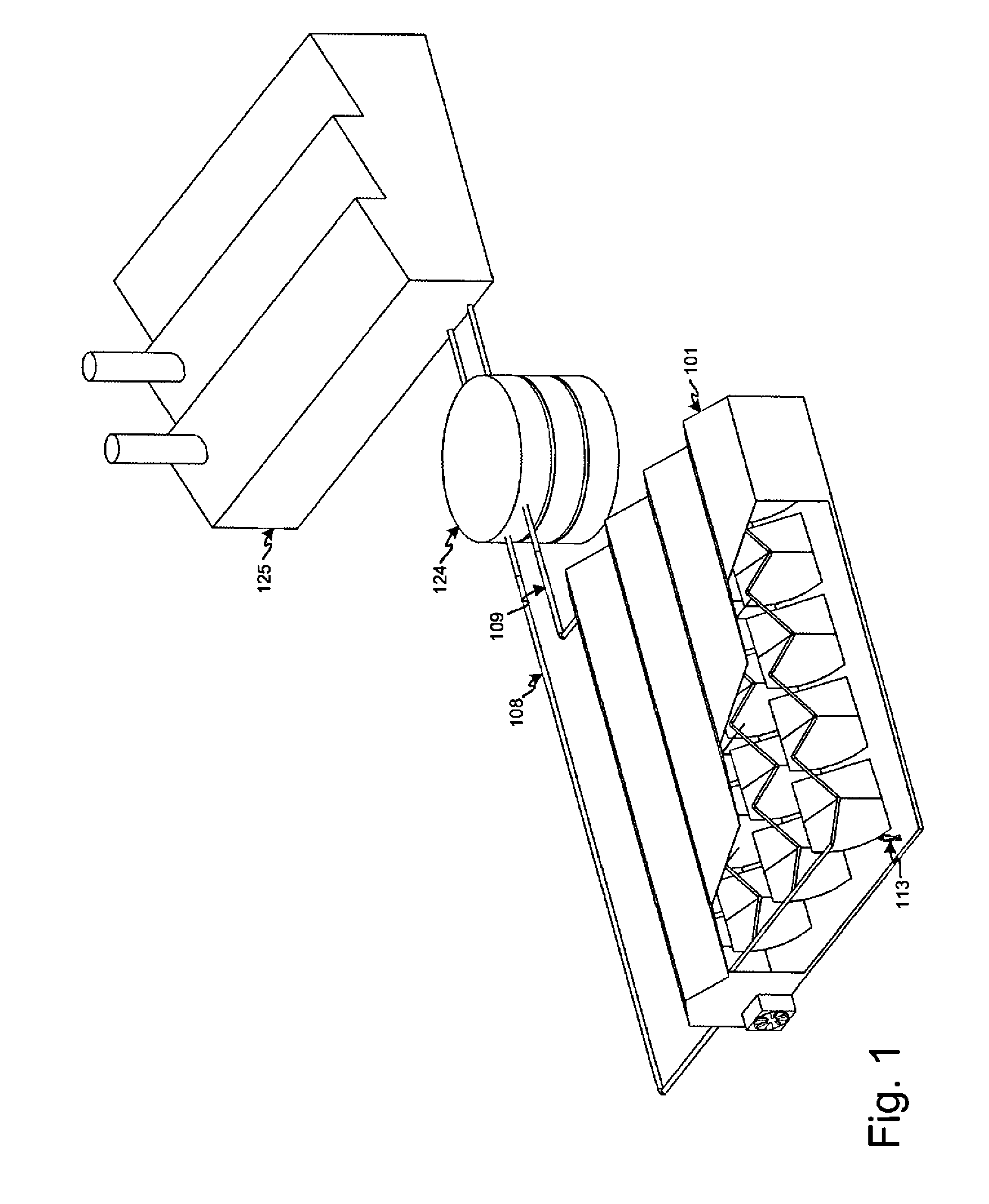
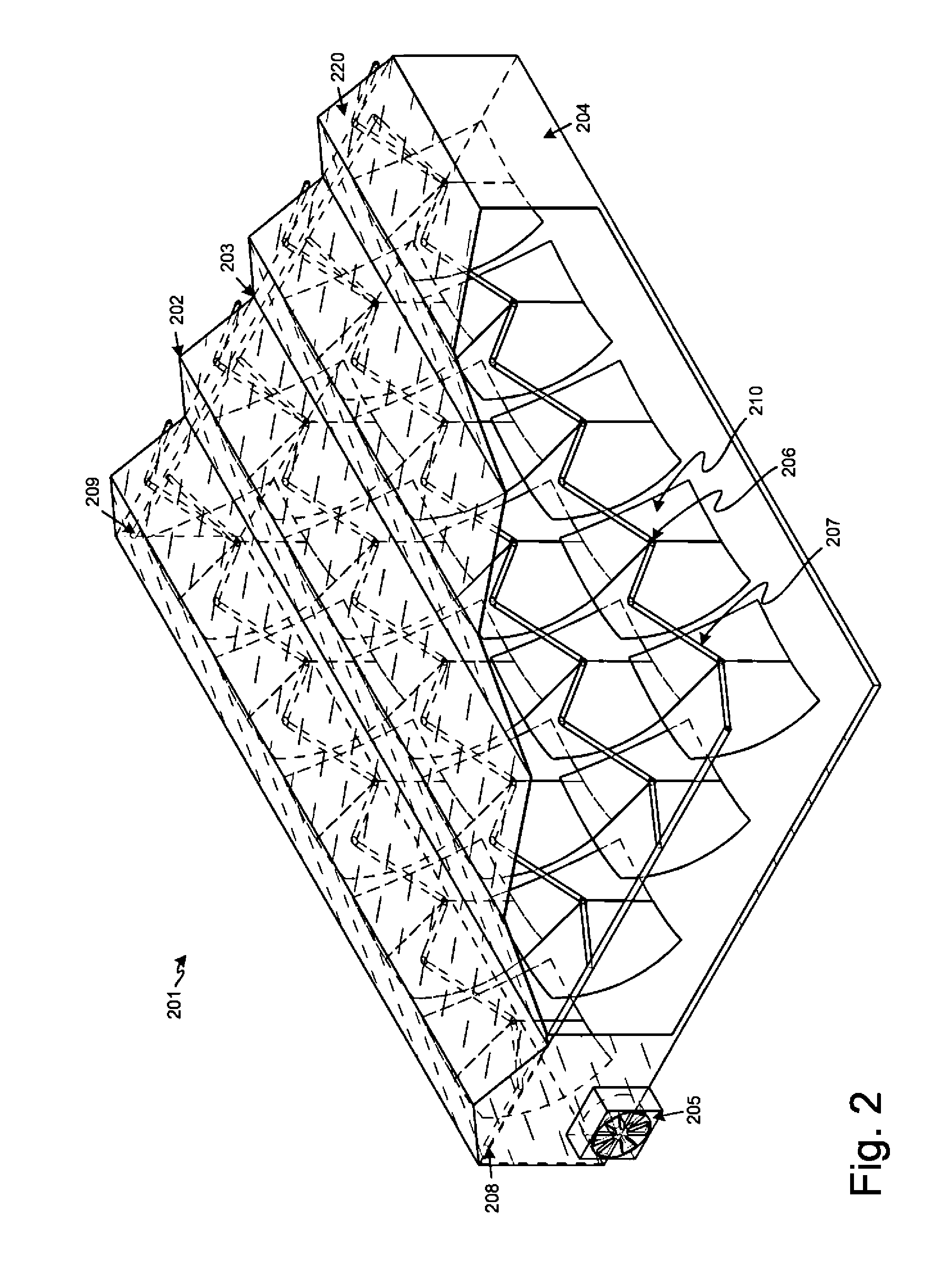
[0051]In various embodiments and / or usage scenarios, the illustrated embodiments are related to each other. For example, in some embodiments, greenhouse 101 of FIG. 1 is an implementation of greenhouse 201 of FIG. 2, with inlet pipe 108 and outlet pipe 109 corresponding respectively to inlet 208 and outlet 209. For another example, in some embodiments, various elements of FIGS. 4A / 4B are implementations of elements in other figures, such as roof peak 402, roof gutter 403, solar receiver 406, thermally insulated pipes 407, and solar concentrator 410, corresponding respectively to peak 202, gutter 203, receiver 206, thermally insulated pipe 207, and solar concentrator 210 of FIG. 2.

[0052]While the forgoing embodiments are described as having roof systems with peaks and gutters, other embodiments use alternate roof systems, such as peaked, arched, mansard, and Quonset-style roof systems, as well as variations and combinations thereof. In various embodiments, a partially transparent pro...


PUM

PropertyMeasurementUnit
thickaaaaaaaaaa
weightaaaaaaaaaa
weightaaaaaaaaaa

Abstract

A protective transparent enclosure (such as a glasshouse or a greenhouse) encloses a concentrated solar power system (e.g. a thermal and / or a photovoltaic system). The concentrated solar power system includes one or more solar concentrators and one or more solar receivers. Thermal power is provided to an industrial process, electrical power is provided to an electrical distribution grid, or both. In some embodiments, the solar concentrators are dish-shaped mirrors that are mechanically coupled to a joint that enables rotation at a fixed distance about respective solar collectors that are fixed in position with respect to the protective transparent enclosure. In some embodiments, the solar collectors are suspended from structure of the protective transparent enclosure and the solar concentrators are suspended from the solar collectors. In some embodiments, the greenhouse is a Dutch Venlo style greenhouse.

Description

CROSS REFERENCE TO RELATED APPLICATIONS[0001]Priority benefit claims for this application are made in the accompanying Application Data Sheet, Request, or Transmittal (as appropriate, if any). To the extent permitted by the type of the instant application, this application incorporates by reference for all purposes the following applications, all owned by the owner of the instant application:[0002]U.S. Provisional Application Ser. No. 61 / 149,292, filed Feb. 2, 2009, first named inventor Rod MacGregor, and entitled Concentrating Solar Power with Glasshouses; and[0003]U.S. Provisional Application Ser. No. 61 / 176,041, filed May 6, 2009, first named inventor Peter Von Behrens, and entitled Concentrating PhotoVoltaics with Glasshouses.BACKGROUND[0004]1. Field[0005]Advancements in concentrated solar thermal power (CST), photovoltaic solar energy (PV), concentrated photovoltaic solar energy (CPV), and industrial use of concentrated solar thermal energy are needed to provide improvements in...

Claims


Application Information

Patent Timeline
Patent Type & Authority Patents(United States)
IPC IPC(8): H01L31/052F24S10/70F24S23/70F24S23/71F24S50/20
CPCY02E10/60H01L31/058F24J2/5417Y02E10/46H01L31/0522Y02E10/42F24J2/1047F24J2/12Y02E10/47Y02E10/52F24J2002/1061G02B7/183H01L31/054Y10T29/49826H01L31/0547H02S40/44A01G9/243F24S23/71F24S23/74F24S23/80F24S30/45F24S2023/84Y02A40/25Y02P60/12Y02P80/20Y02E10/40
Inventor MACGREGOR, RODERICKVON BEHRENS, PETER EMERY
Owner GLASSPOINT SOLAR
Learn More