
Method to maximize loudspeaker sound pressure level with a high peak to average power ratio audio source

a loudspeaker and peak power ratio technology, applied in the field of loudspeaker systems, can solve the problems of permanent damage or failure of the loudspeaker, affecting the reproduction of output sound, and causing the risk of overdriving the loudspeaker

Active Publication Date: 2014-06-10
HARRIS GLOBAL COMM INC
View PDF36 Cites 11 Cited by
  • Summary
  • Abstract
  • Description
  • Claims
  • Application Information

AI Technical Summary

Benefits of technology

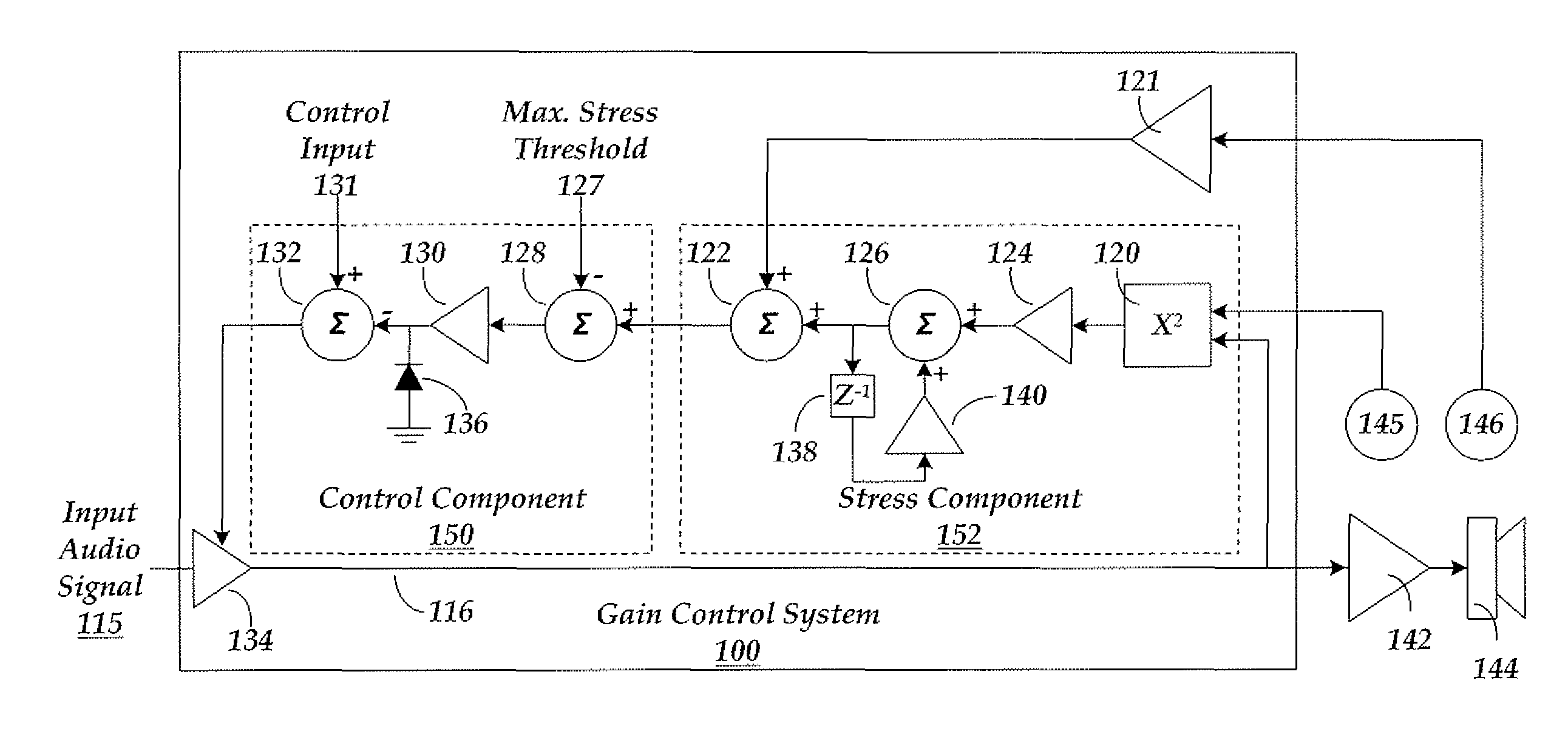
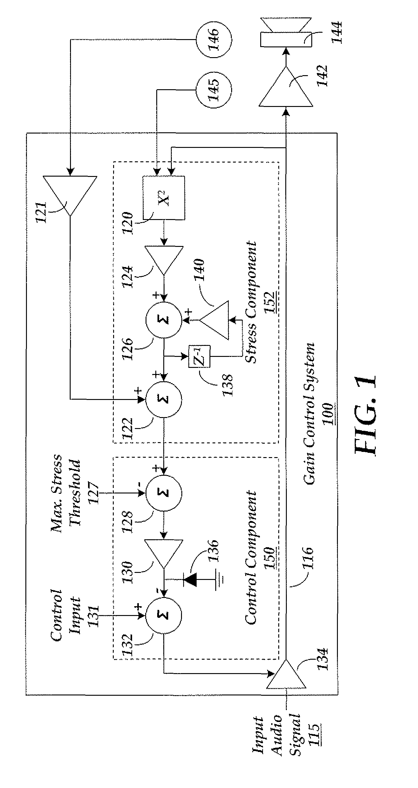
[0009]The stress component is advantageously configured to determine the stress value using a time constant associated with the loudspeaker. In effect, the time constant is used to model certain characteristics of the loudspeaker. For example, the stress component in some embodiments is configured to determine the stress value by modeling the thermal response of the loudspeaker. In other embodiments, the stress component is configured to estimate a cumulative mechanical stress resulting from vibration on the loudspeaker over a predetermined period of time. In still further embodiments the stress component can be a simple electronic circuit that limits a maximum amount of energy that can be delivered to the loudspeaker over some predetermined period of time. For example, the maximum amount of energy can be based on a manufacturer's specification for the maximum power handling capability of the loudspeaker.
[0010]The stress component can be arranged to evaluate any parameter that stresses the operation of the loudspeaker. For example, such stresses can involve mechanical, electrical, electro-mechanical, acoustic, or temperature stress, without limitation. For example, in some embodiments of the invention, the stress component is implemented more particularly as a temperature component. The temperature component, the control component, and the gain component work together to provide a gain controlled audio signal for the loudspeaker. The gain of this audio signal is selectively controlled by these components in order to protect the loudspeaker from being overdriven.
[0014]Aspects of the present invention also include at least an apparatus and method for maximizing a sound pressure level of a loudspeaker while preventing damage or distortion thereto.

Problems solved by technology

However, driving a loudspeaker near its operational limits incurs a risk of overdriving the loudspeaker.
Overdriving a loudspeaker may disrupt the reproduction of an output sound in various manners.
For example, overdriving a loudspeaker may cause elements of the loudspeaker to overheat, resulting in permanent damage or failure of the loudspeaker.
Overdriving a loudspeaker may also risk distortion of the output sound, resulting in an abrupt and unpleasant attenuation of the output sound.
The risk of overdriving a loudspeaker may be further complicated by environmental conditions, such as ambient temperature extremes in the environment of use.
Such environmental conditions can cause a loudspeaker associated with a portable radio system to reach its operational limits at comparatively lower drive levels.
Yet, these schemes remain deficient in providing a proper degree of protection.
For example, simple schemes involving feedback of an audio signal may not be able to prevent loudspeaker damage under unusual signal conditions, including when a protection scheme is unable to quickly respond.
Moreover, simple protection schemes that rely on the level of an applied audio signal may not adequately account for one or more other time varying factors associated with a loudspeaker, such as a temperature, a period of time over which the audio signal is applied, and a waveform shape of the audio signal.
That is, simple protection schemes may overprotect a loudspeaker at the expense of an otherwise preferable and achievable output sound pressure level.

Method used


Image

  • Method to maximize loudspeaker sound pressure level with a high peak to average power ratio audio source
  • Method to maximize loudspeaker sound pressure level with a high peak to average power ratio audio source
  • Method to maximize loudspeaker sound pressure level with a high peak to average power ratio audio source

Examples


Embodiment Construction

[0019]Throughout the specification and claims, the following terms take the meanings explicitly associated herein, unless the context clearly dictates otherwise. The phrase “in one embodiment” as used herein does not necessarily refer to the same embodiment, though it may. Furthermore, the phrase “in another embodiment” as used herein does not necessarily refer to a different embodiment, although it may. Thus, as described below, various embodiments of the invention may be readily combined, without departing from the scope or spirit of the invention.

[0020]In addition, as used herein, the term “or” is an inclusive “or” operator, and is equivalent to the term “and / or,” unless the context clearly dictates otherwise. The term “based on” is not exclusive and allows for being based on additional factors not described, unless the context clearly dictates otherwise. In addition, throughout the specification, the meaning of “a,”“an,” and “the” include plural references. The meaning of “in” i...


PUM


Abstract

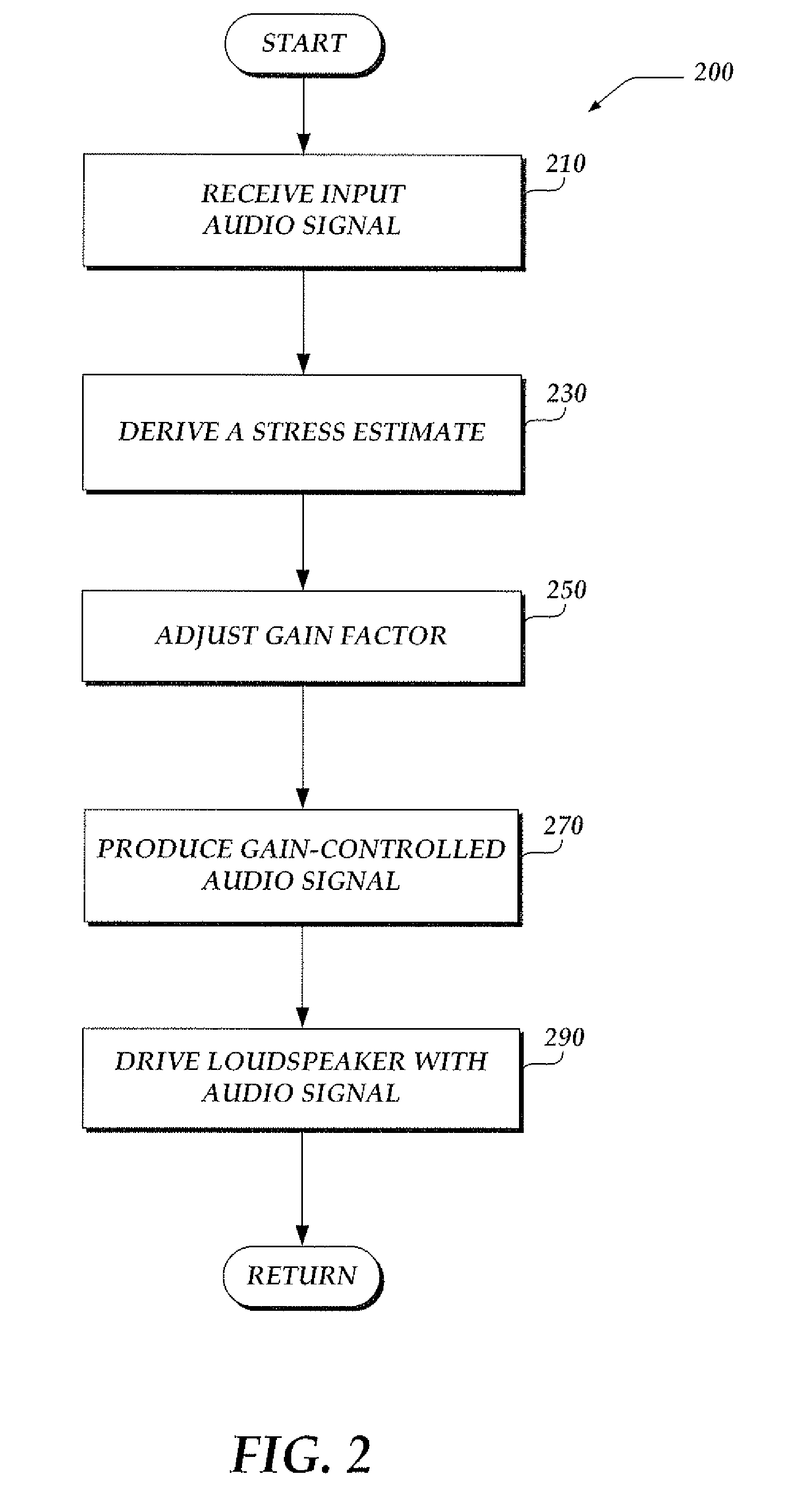
A system is provided to protect a loudspeaker (144) by controlling a level of an applied audio signal. A control signal is generated by applying an input audio signal (115) to the collective operations of a gain control system (100). The gain control system (100) uses the input audio signal (115) in conjunction with at least one parameter to derive an estimated stress associated with the loudspeaker (144). The estimated stress is compared with a protection threshold stress (127). If the protection threshold stress is exceeded, a gain applied by a gain component (134) is selectively adjusted to modify the input audio signal (115). The resulting gain-controlled audio signal (116) is employed to drive the loudspeaker (144).

Description

BACKGROUND OF THE INVENTION[0001]1. Statement of the Technical Field[0002]The invention is directed to a loudspeaker system. In particular, the invention is directed to a system which protects a loudspeaker while maximizing the power that can be input to the loudspeaker.[0003]2. Description of the Related Art[0004]Sound reproduced by a portable handheld radio transceiver system is required to be loud enough to remain intelligible among environmental noises. For a small loudspeaker within a portable handheld radio transceiver system, this loudness may be achieved by driving the loudspeaker near its operational limits. However, driving a loudspeaker near its operational limits incurs a risk of overdriving the loudspeaker.[0005]Overdriving a loudspeaker may disrupt the reproduction of an output sound in various manners. For example, overdriving a loudspeaker may cause elements of the loudspeaker to overheat, resulting in permanent damage or failure of the loudspeaker. Overdriving a lou...

Claims


Application Information

Patent Timeline
Patent Type & Authority Patents(United States)
IPC IPC(8): H03G11/00
CPCH04R2420/07H04R3/007H04R2499/11H04R2430/01
Inventor MARTZ, DONALDTENNANT, BRYCEKEANE, ANTHONY RICHARD ALAN
Owner HARRIS GLOBAL COMM INC
Learn More