Audio data receiving apparatus, audio data receiving method, and audio data transmission and receiving system

a technology for audio data and receiving apparatus, applied in the direction of recording information storage, recording signal processing, instruments, etc., can solve the problems of asynchronous noise, asynchronous noise, and a clock on the receiving side becoming unstable, so as to suppress the effect of a decrease in the quality of audio

Inactive Publication Date: 2014-06-10
SONY CORP
View PDF9 Cites 124 Cited by
  • Summary
  • Abstract
  • Description
  • Claims
  • Application Information

AI Technical Summary

Benefits of technology

[0008]Accordingly, it is desirable to provide a new and improved audio data receiving apparatus, audio data receiving method, and audio data transmission and receiving system that are capable of suppressing a decrease in the quality of audio on a receiving side in a case where audio data is to be transmitted among a plurality of apparatuses.
[0010]With such a configuration, the received audio data is demodulated in accordance with a second clock signal having a frequency synchronized with the sampling frequency of the audio data. Then, the demodulated audio data is oversampled using a frequency higher than the second clock signal, and thereafter is sequentially output in accordance with a third stable clock signal. As a result, for example, asynchronous noise based on a deviation between the clock on the transmission side and the clock on the receiving side is removed, and a decrease in the quality of the audio due to an unstable clock is prevented.
[0015]As has been described above, according to the audio data receiving apparatus, the audio data receiving method, and the audio data transmitting and receiving system in accordance with embodiments of the present invention, it is possible to suppress a decrease in the quality of audio on a receiving side in a case where audio data is to be transmitted among a plurality of apparatuses.

Problems solved by technology

However, in the synchronous mode, there is a case in which a clock on a receiving side becomes unstable due to the performance of a phase-locked loop (PLL) circuit that extracts clock components from a received signal and due to influence of noise contained in the received signal, and the quality of reproduced audio is decreased.
Furthermore, in the asynchronous mode, there is a case in which as a result of a deviation occurring between the clock on a transmission side and the clock on a receiving side, asynchronous noise occurs.

Method used


Image

  • Audio data receiving apparatus, audio data receiving method, and audio data transmission and receiving system
  • Audio data receiving apparatus, audio data receiving method, and audio data transmission and receiving system
  • Audio data receiving apparatus, audio data receiving method, and audio data transmission and receiving system

Examples


Embodiment Construction

[0024]Preferred embodiments of the present invention will be described in detail below with reference to the attached drawings. Components in the present specification and the drawings, which have substantially the same functional configurations, are designated with the same reference numerals, and repeated description thereof is omitted.

[0025]The “embodiments of the present invention” will be described in the following order.

[0026]1. Overview of System

[0027]1-1. Example of System Configuration

[0028]1-2. Description of Technology Related to the Present Invention

[0029]2. Description of Embodiment

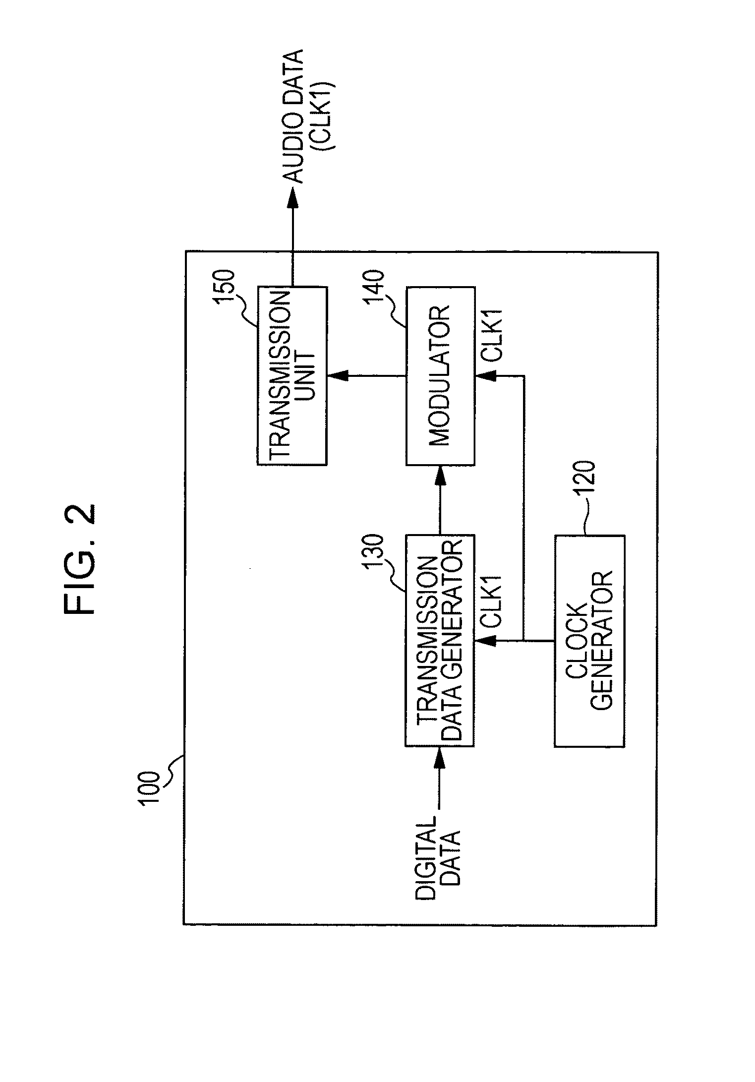
[0030]2-1. Example of Configuration of Transmission Apparatus

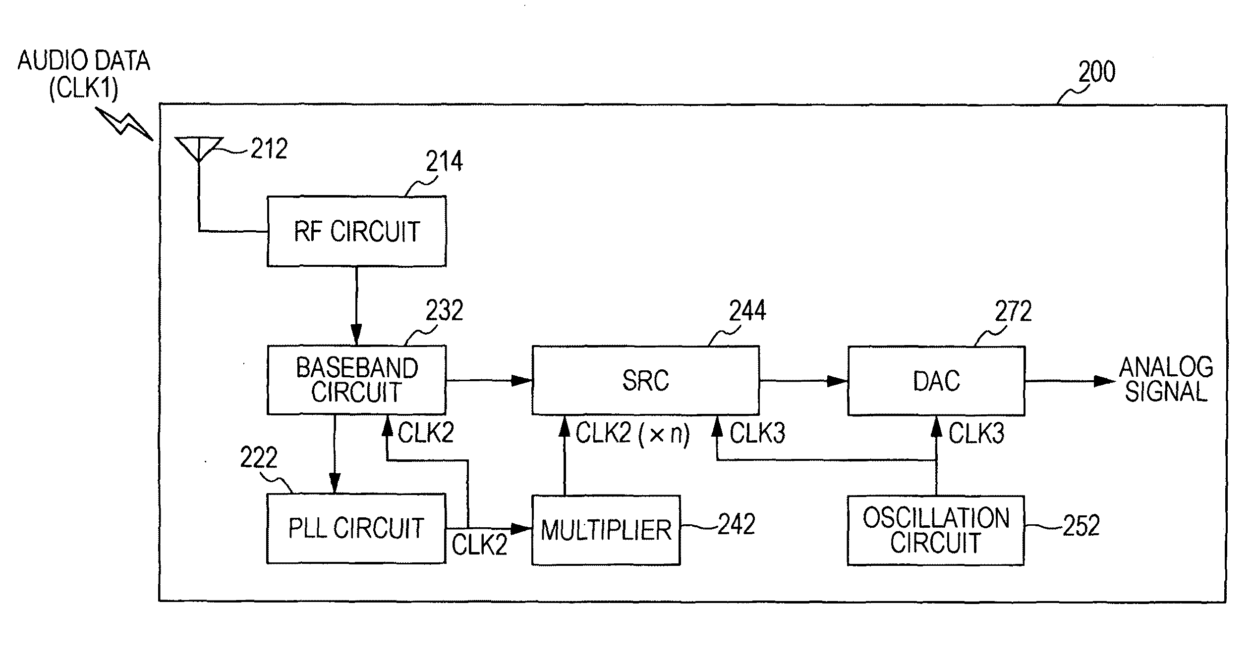
[0031]2-2. Example of Configuration of Receiving Apparatus

[0032]3. Summary

1. Overview of System

1-1. Example of Configuration of System

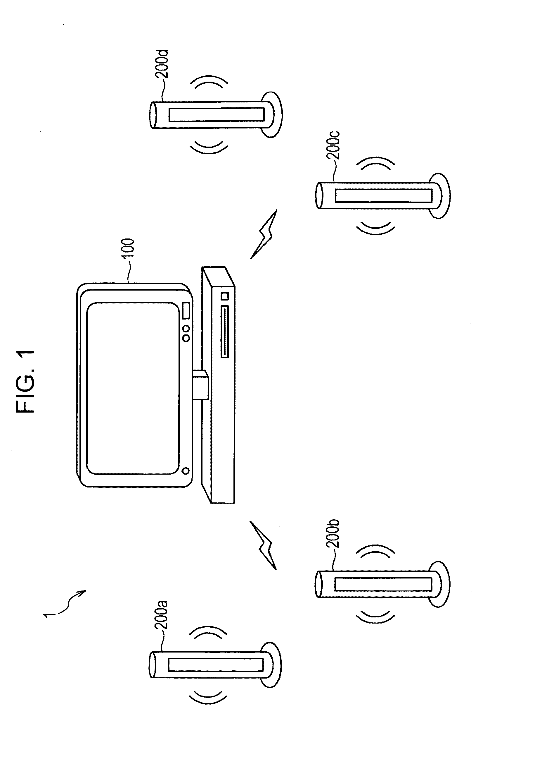
[0033]FIG. 1 is a schematic view showing the overview of an audio data transmission and receiving system 1 according to an embodiment of the present invention. Referring to FIG. 1, the audio data tran...


PUM

PropertyMeasurementUnit
frequencyaaaaaaaaaa
frequencyaaaaaaaaaa
frequencyaaaaaaaaaa

Abstract

An audio data receiving apparatus includes a receiving unit configured to receive audio data sampled in accordance with a first clock signal; a synchronization unit configured to generate a second clock signal that is synchronized with the first clock signal by extracting clock components contained in the audio data; a demodulator configured to demodulate the audio data in accordance with the second clock signal; an oversampling unit configured to oversample the audio data demodulated by the demodulator by using a frequency higher than a frequency of the second clock signal; a clock generator configured to generate a third clock signal having a frequency nearly equal to the first clock signal; and a data output unit configured to output the audio data oversampled by the oversampling unit in accordance with the third clock signal generated by the clock generator.

Description

CROSS-REFERENCE TO RELATED APPLICATION[0001]The present application claims priority from Japanese Patent Application No. JP 2009-140404 filed in the Japanese Patent Office on Jun. 11, 2009, the entire content of which is incorporated herein by reference.BACKGROUND OF THE INVENTION[0002]1. Field of the Invention[0003]The present invention relates to an audio data receiving apparatus, an audio data receiving method, and an audio data transmission and receiving system.[0004]2. Description of the Related Art[0005]In recent years, as information transmission technology has become developed, a technology for transmitting audio data among a plurality of apparatuses has become increasingly used. For example, in home theater systems, attempts have been made to increase the degree of freedom of a layout of a speaker or the like by connecting a transmission apparatus that transmits audio data to a receiving apparatus that receives audio data, such as a speaker, in a wireless manner.[0006]As de...

Claims


Application Information

Patent Timeline
Patent Type & Authority Patents(United States)
IPC IPC(8): H04R5/02H04L7/00G11B20/00
CPCG11B20/10425G11B20/10009G11B20/10527
Inventor SATO, TEPPEISHIBA, KENJISUZUKI, SATORU
Owner SONY CORP
Why Eureka
Try Eureka