Gripper device for transporting racks

a technology for racks and grippers, which is applied in the direction of manipulators, load-engaging elements, metal-working hand tools, etc., can solve the problems of limited function of gripper devices, device not suited for rack processing purposes, and cannot be used in coverslippers, etc., and achieve the effect of reducing the cost of manufactur

Active Publication Date: 2014-06-17
LEICA BIOSYST NUSSLOCH
View PDF23 Cites 8 Cited by
  • Summary
  • Abstract
  • Description
  • Claims
  • Application Information

AI Technical Summary

Benefits of technology

[0007]It is, therefore, an object of the present invention to provide a gripper device of the above-mentioned type which can be used in a versatile manner in automated stainers and coverslippers and contributes to reducing the cost of manufacture.
[0008]This object is achieved according to the present invention in that the gripping sections are provided with separate first and second profiles, the first profile being configured for gripping the rack in a vertical position, and the second profile being configured for gripping the rack in a horizontal position. Thus, the functions of several transport devices having different gripping members can advantageously be integrated into one transport device having only one gripper device. The second profile is configured such that a horizontally oriented rack may be grasped and transported, for example, by its handle, such as is frequently required in stainers where the entire rack is immersed in a staining container. The first profile is configured for grasping the rack in the vertical orientation, which allows the rack to be transferred to or inserted into specific processing stations of the coverslipper. Since the rack can be grasped at different positions, it is possible to satisfy a wide variety of requirements with respect to transport in automated stainers and coverslippers. Instead of using multiple transport systems having differently configured grippers, one single transport device may be used in versatile manner. For example, a rack coming from a stainer may first be transported to a coverslipper and deposited at a suitable position therein. The rack may be turned by a separate rotating device in order to orient the slides horizontally for the subsequent coverslipping process. The rack may then be transferred to a coverslipping station by the same gripper device. The inventive design significantly reduces the cost of manufacture of such automated systems.
[0009]It has proven to be particularly advantageous when the second profile is configured for gripping a rack handle. This allows a high level of safety during transport and makes it easier to transport the racks when they are introduced into the automated system. In a further embodiment, the first profile is configured for gripping the rack basket and is advantageously matched to the outer contour of the rack basket.
[0010]In yet another embodiment of the present invention, the gripping arms are connected to a translationally movable thrust member, so that the gripping arms can be opened and closed by a translational movement of the thrust member. Thus, the gripper device can be made small and compact, and at the same time simple in construction. Moreover, it is possible to convert small actuating forces into large gripping forces. The drive has correspondingly small dimensions.
[0011]In a further development of the inventive concept, the thrust member may be a conical threaded nut which is threaded onto a threaded spindle and guided in the gripper device such that it is translationally movable but rotationally immovable, so that a rotational movement of the threaded spindle produces a translational movement of the threaded nut. While other devices require motor or pneumatic drives dimensioned large enough to provide large gripping forces, the drive mechanism of the present invention is capable of producing large forces while keeping complexity and space requirements to a minimum.
[0012]Advantageously, an electric, pneumatic or hydraulic drive is used for moving the thrust member. For example, it is possible to use a rotary drive for the threaded spindle. In this way, the requirement of small space at large gripping forces can be satisfied.

Problems solved by technology

In this connection, the function of the gripper device is limited to lifting the racks and transporting them further on.
However, this device is not suited for rack processing purposes and cannot be used in coverslippers where the entire rack is turned and subsequently transferred to the coverslipping station.
Rather, an additional gripper device specifically tailored to the turned rack would be needed, making the entire system more costly and complex.

Method used


Image

  • Gripper device for transporting racks
  • Gripper device for transporting racks
  • Gripper device for transporting racks

Examples


Embodiment Construction

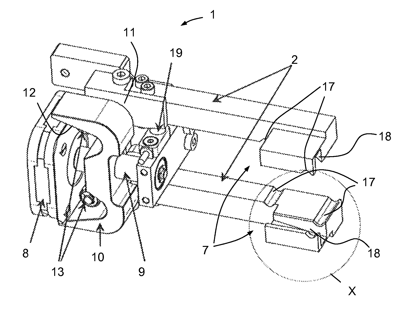
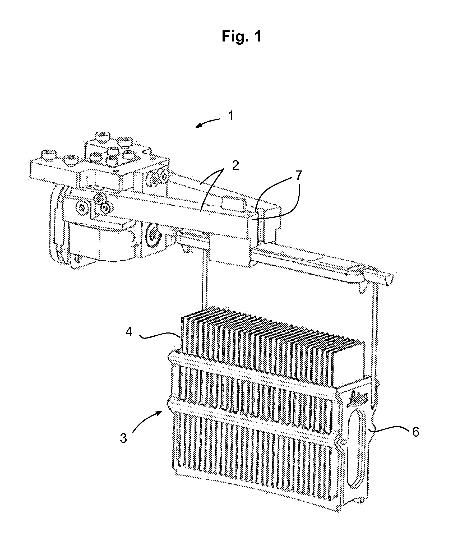
[0023]Gripper device 1, as shown in FIG. 1, has two gripping arms 2 for holding a rack 3, in which slides 4 are inserted vertically side by side. Rack 3 has a handle 5 from which is suspended a basket 6 of rack 3. The forward ends of gripper arms 2 are configured as gripping sections 7 for grasping handle 5. A transport device (not shown) connected to gripper device 1 can transport rack 3 by means of handle 5. In particular, when the rack is transported within a stainer, or when the rack is lowered into input cuvettes in a coverslipper and removed therefrom, transport is performed with the track in the horizontal orientation shown in FIG. 1, since the vertical orientation of slides 4 in rack 3 ensures that the stain can run off the tissue sample in the best possible way.

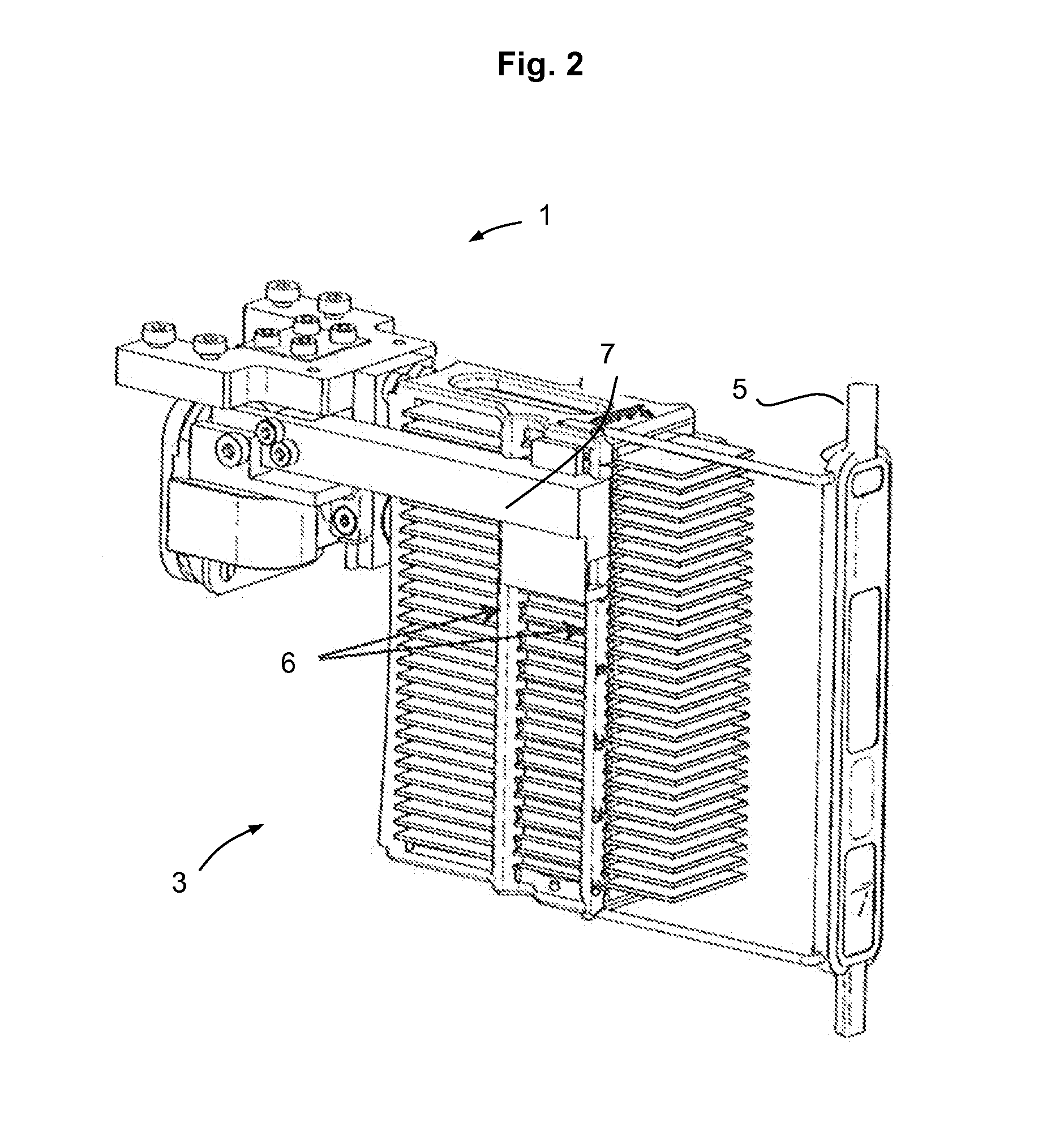
[0024]However, prior to a coverslipping operation, rack 3 must be turned in order to orient slides 4 horizontally. As shown in FIG. 2, gripper device 1 is also capable of grasping a rack 3 that has been turned. In th...


PUM


Abstract

The present invention relates to a gripper device for transporting a rack (3) for microscope slides (4), in particular in systems for preparing tissue samples for histological examinations, the gripper device having a gripping mechanism including a pair of gripping arms (2), whose ends are configured as gripping sections (7) for gripping the rack. In order to provide a gripper device which can be used in a versatile manner in automated stainers and coverslippers and contributes to reducing the cost of manufacture, it is proposed that the gripping sections (7) be provided with first profiles (17) for gripping the rack (3) in a vertical position and second profiles (18) for gripping the rack (3) in a horizontal position.

Description

CROSS REFERENCE TO RELATED APPLICATIONS[0001]This application claims priority of German patent application number 10 2011 110 250.0 filed May 13, 2011, the entire disclosure of which is incorporated by reference herein.FIELD OF THE INVENTION[0002]The present invention relates to a gripper device for transporting a rack for microscope slides, in particular in systems for preparing tissue samples for histological examinations, the gripper device having a gripping mechanism including a pair of gripping arms, whose ends are configured as gripping sections for gripping the rack.BACKGROUND OF THE INVENTION[0003]Such devices are used, in particular, in systems where stained specimens or tissue samples, such as histological sections, placed on slides are provided with a cover slip for later analysis under a microscope. The staining of the specimens is performed in automated stainers, in which the slides carrying the tissue samples are sorted into racks or slide holders and immersed therewit...

Claims


Application Information

Patent Timeline
Patent Type & Authority Patents(United States)
IPC IPC(8): B25J15/02
CPCB25J15/0206B25J15/0033
Inventor HAJROVIC, MIDHAT
Owner LEICA BIOSYST NUSSLOCH
Why Eureka
Try Eureka